Steel pipe cutting device
A cutting device and steel pipe technology, applied in the direction of pipe shearing device, shearing device, accessory device of shearing machine, etc., can solve the problems of reducing the scope of application and inconvenient adjustment of cutting surface, so as to increase the scope, improve the cutting efficiency, Guaranteed effect of accuracy
- Summary
- Abstract
- Description
- Claims
- Application Information
AI Technical Summary
Problems solved by technology
Method used
Image
Examples
Embodiment Construction
[0025] The following is further described in detail through specific implementation methods:
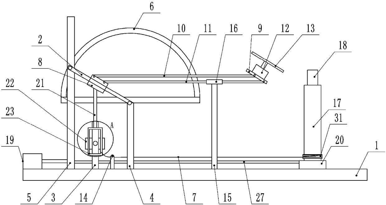
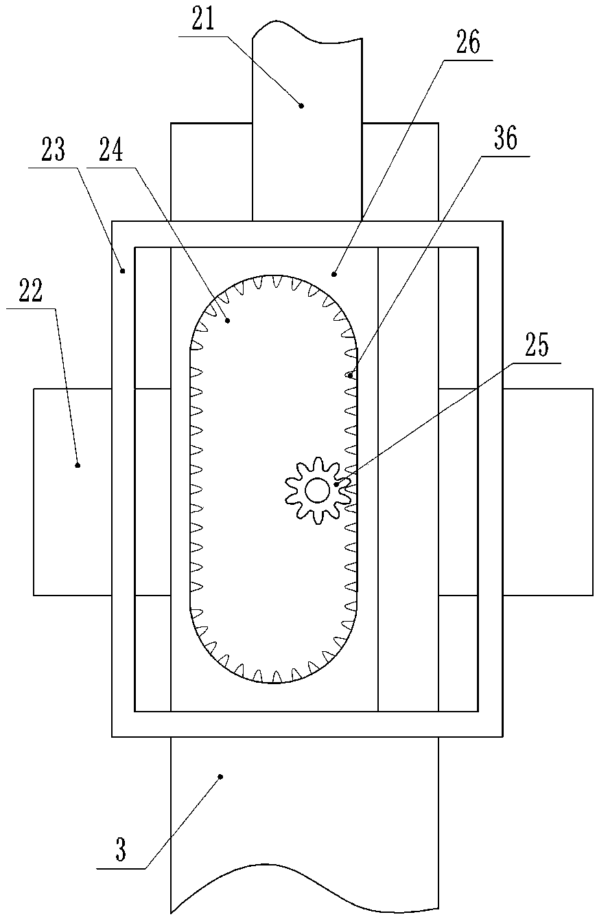
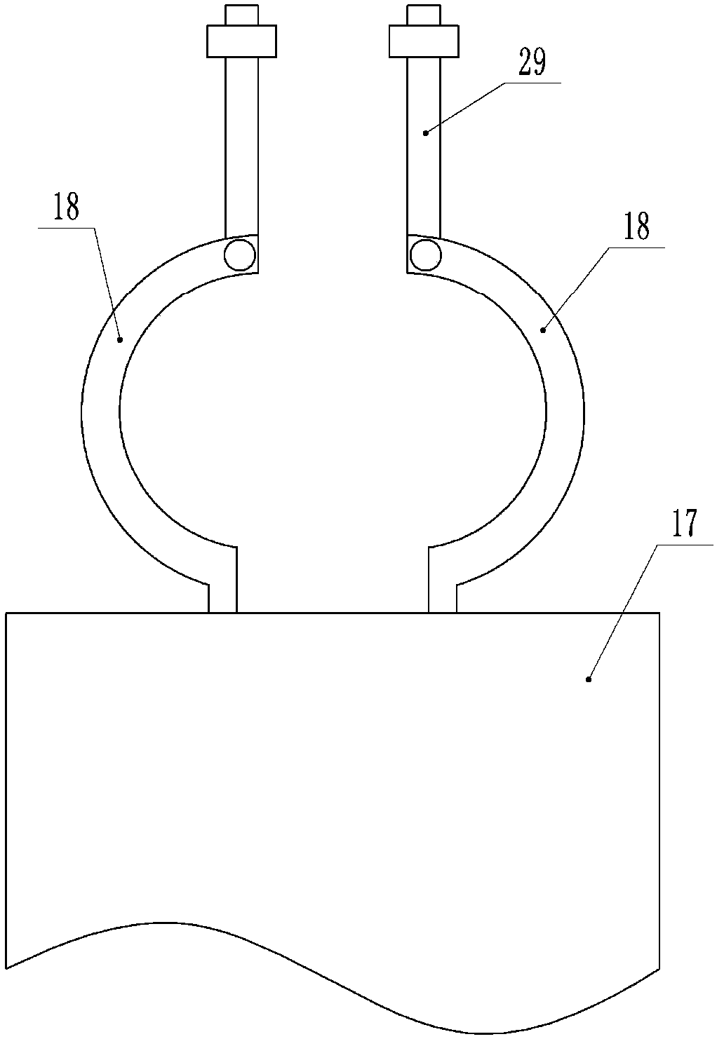
[0026] The reference signs in the drawings of the description include: base 1, installation rod 2, support rod 3, short support rod 4, long support rod 5, guide rail 6, string 7, mounting base 8, mounting plate 9, first ejector rod 10. The second ejector rod 11, the first motor 12, the cutting knife 13, the roller 14, the telescopic rod 15, the sliding sleeve 16, the working table 17, the jacket 18, the cylinder 19, the sliding seat 20, the third ejector rod 21, Second motor 22, sliding frame 23, annular ring 24, gear 25, sliding plate 26, fourth ejector rod 27, groove 28, buckle 29, protrusion 30, sleeve 31, ratchet 32, pawl 33, positioning block 34 , stop block 35 , first protruding tooth 36 , and second protruding tooth 37 .
[0027] as attached figure 1 As shown, a steel pipe cutting device includes a base 1, a mounting rod 2 and a vertical support rod 3, the support rod 3 is s...
PUM
 Abstract
Description
Claims
Application Information
 - R&D
- Intellectual Property
- Life Sciences
- Materials
- Tech Scout
- Unparalleled Data Quality
- Higher Quality Content
- 60% Fewer Hallucinations
Browse by: Latest US Patents, China's latest patents, Technical Efficacy Thesaurus, Application Domain, Technology Topic, Popular Technical Reports.
© 2025 PatSnap. All rights reserved.Legal|Privacy policy|Modern Slavery Act Transparency Statement|Sitemap|About US| Contact US: help@patsnap.com


