A honeycomb material ultrasonic cutting test platform
A technology of ultrasonic cutting and honeycomb materials, applied in the direction of metal processing equipment, measuring/indicating equipment, metal processing machinery parts, etc., to achieve a variety of test effects
- Summary
- Abstract
- Description
- Claims
- Application Information
AI Technical Summary
Problems solved by technology
Method used
Image
Examples
Embodiment 1
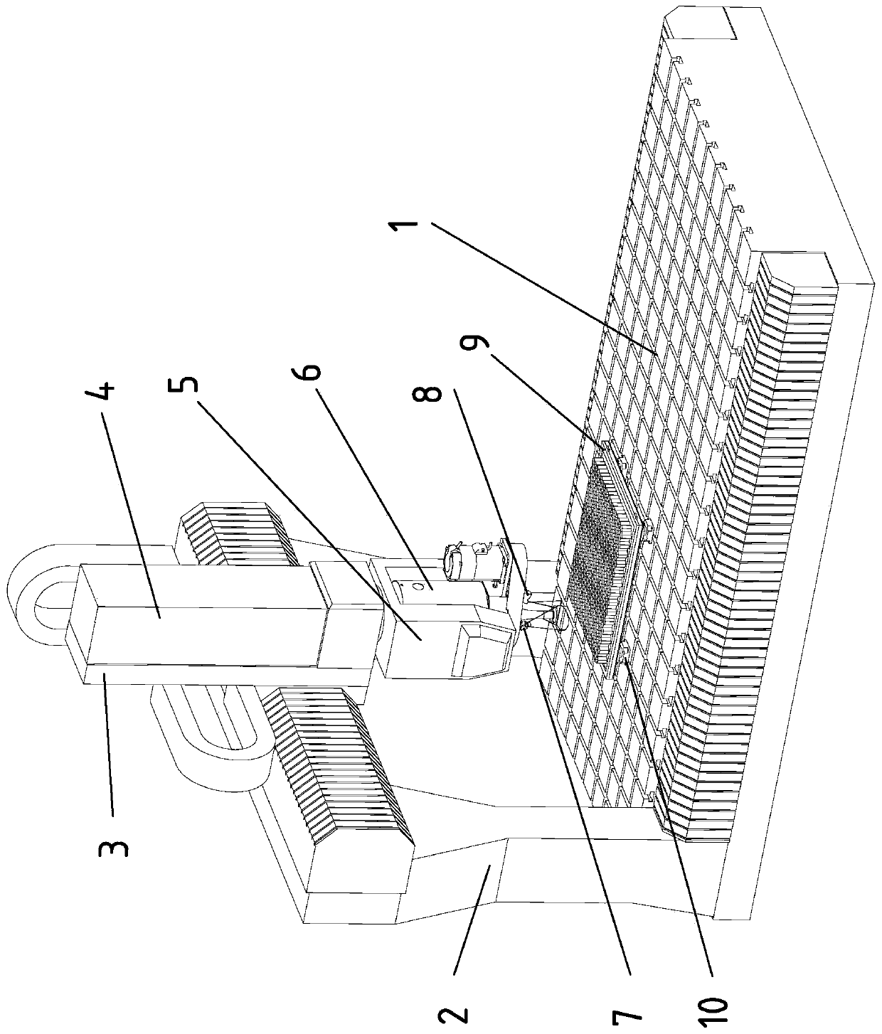
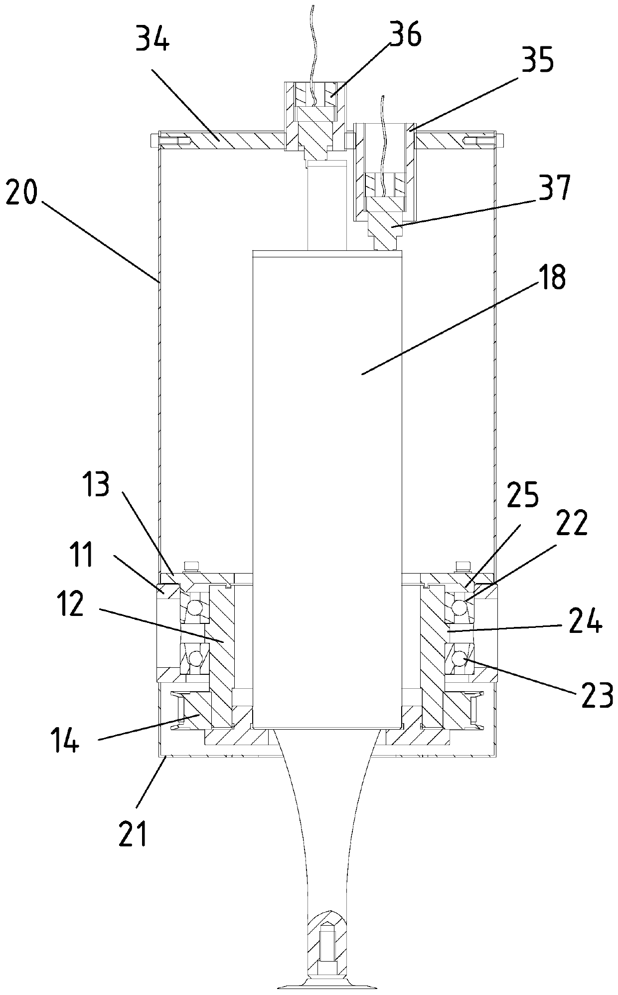
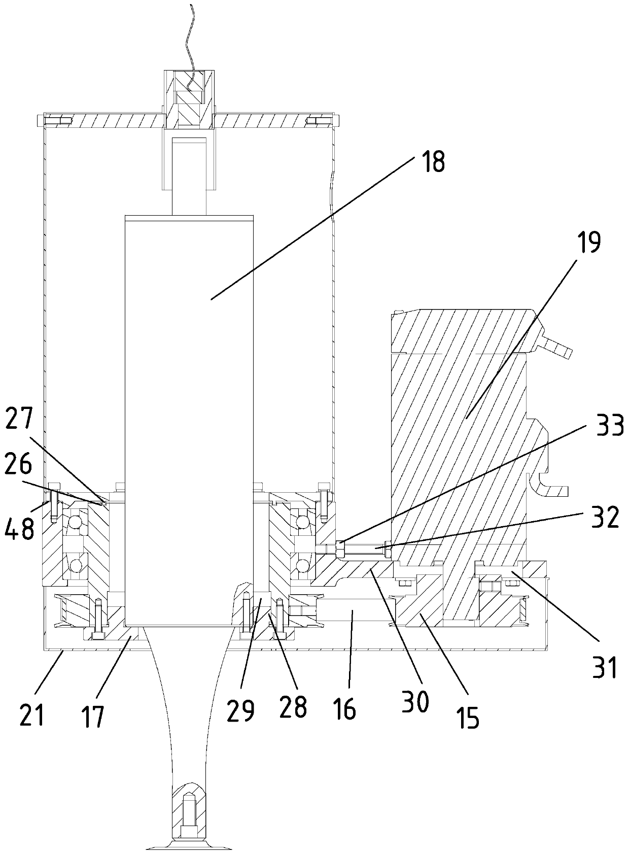
[0045] Such as Figure 1-Figure 8 As shown, a honeycomb material ultrasonic cutting test platform includes: five-axis motion platform (including workbench 1, Y-axis slide table 2, X-axis slide table 3, Z-axis slide table 4, A / C swing head 5), Ultrasonic cutting special mechanical spindle device 6, cutting temperature measuring device 7, ultrasonic vibration performance measuring device 8, honeycomb material clamping device 9 and cutting force measuring device 10, said ultrasonic cutting special spindle device 6 is fixed on the A / C pendulum On the head 5, the cutting force measuring device 10 is fixed on the workbench 1, the honeycomb material clamping device 9 is fixed on the cutting force measuring device 10, the cutting temperature measuring device 7 and the ultrasonic The vibration performance measuring device 8 is fixed on the said ultrasonic cutting special spindle device 6 .
[0046] The special mechanical spindle device 6 for ultrasonic cutting includes: an outer sleev...
Embodiment 2
[0061] Such as Figure 9 and 10 As shown, a test platform for ultrasonic cutting of honeycomb materials, the difference between it and Embodiment 1 is that the output end of the ultrasonic vibration system 18 is equipped with a straight-edged sharp knife.
[0062] When working, the servo motor 19 is controlled by the servo motor control system, and through the pulley drive, it provides the ultrasonic vibration system 18 with rotational motion, which can realize the fine adjustment of the direction of the straight edge sharp knife. After determining the direction of the cutting edge, the servo motor control system controls the braking of the servo motor 19 to keep the cutting edge moving in the direction required by the test. The mechanical spindle device 6 dedicated for ultrasonic cutting can be rotated by the A / C swing head 5 to obtain different tool inclination angles. Experimental research on cutting honeycomb materials by using the straight-edged pointed knife under diff...
Embodiment 3
[0064] Such as Figure 11-Figure 13 As shown, a honeycomb material ultrasonic cutting test platform, the difference between it and Example 1 is that the honeycomb material clamping device 9 is a honeycomb material vacuum adsorption clamping device; the honeycomb material vacuum adsorption clamping device includes a vacuum Adsorption platform 49 and vacuum generator.
[0065] When working, the vacuum adsorption platform 49 is installed on the upper end of the cutting force measuring device 10, the lower end of the honeycomb material is pasted with a film or metal plate, the honeycomb material is placed on the vacuum adsorption platform 49, and the vacuum generating device is started. Realize the vacuum adsorption clamping of the honeycomb material; after the test is over, turn off the vacuum generating device, the negative pressure of the vacuum adsorption platform 49 disappears, and the honeycomb material is removed.
PUM
 Abstract
Description
Claims
Application Information
 - R&D
- Intellectual Property
- Life Sciences
- Materials
- Tech Scout
- Unparalleled Data Quality
- Higher Quality Content
- 60% Fewer Hallucinations
Browse by: Latest US Patents, China's latest patents, Technical Efficacy Thesaurus, Application Domain, Technology Topic, Popular Technical Reports.
© 2025 PatSnap. All rights reserved.Legal|Privacy policy|Modern Slavery Act Transparency Statement|Sitemap|About US| Contact US: help@patsnap.com


