
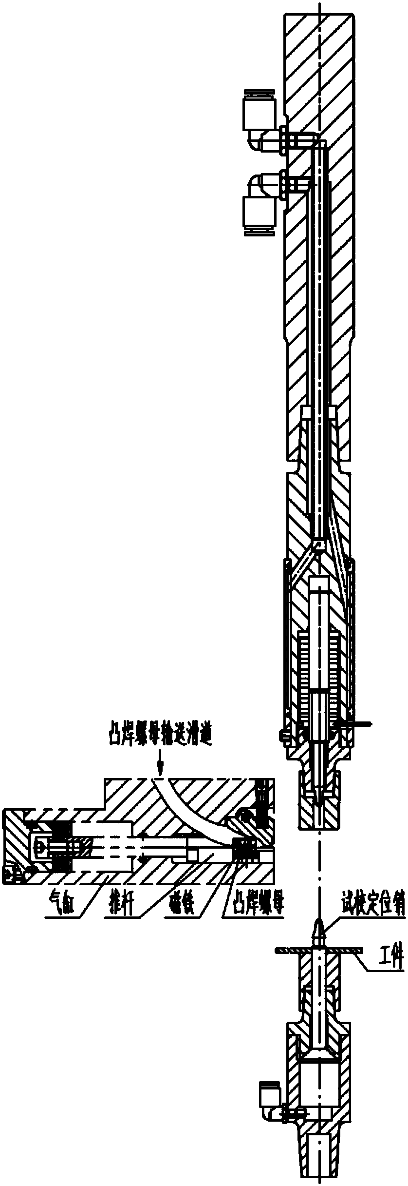
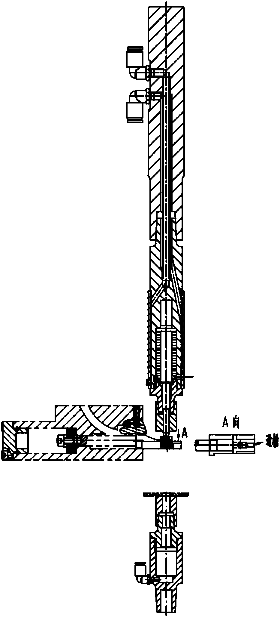
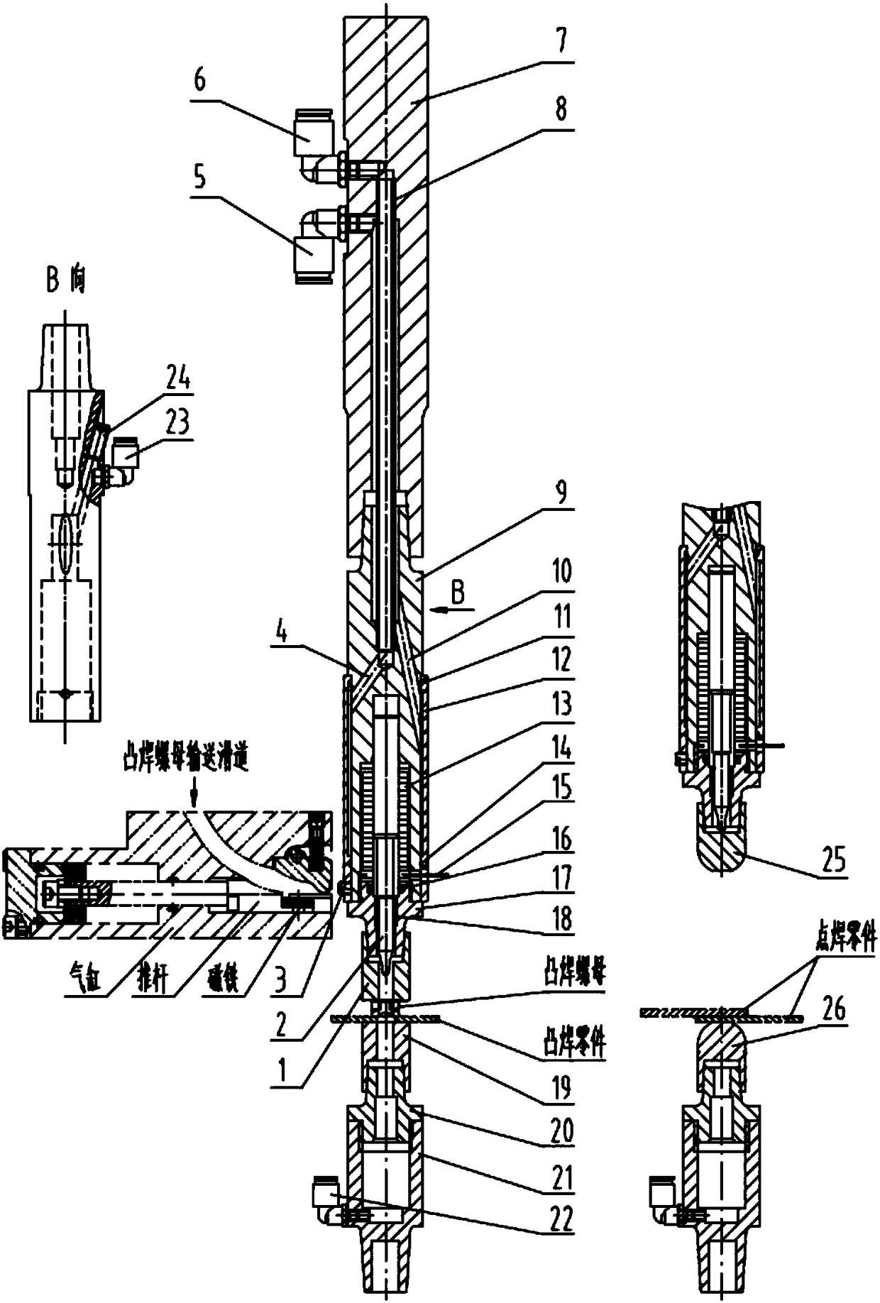
Welding gun automatic projection welding and spot welding structure

An automatic, welding torch technology, applied in welding equipment, resistance welding equipment, resistance electrode holder, etc., to achieve the effect of improving production tempo, reducing production cost and simple structure

Inactive Publication Date: 2018-08-24
上海兰盈智能科技有限公司
View PDF9 Cites 1 Cited by
  • Summary
  • Abstract
  • Description
  • Claims
  • Application Information

AI Technical Summary

Problems solved by technology

[0005] In order to overcome the deficiencies of the prior art, the present invention provides a welding torch that can automatically replace the upper and lower electrodes of projection welding and spot welding, and completes the automatic switching structure of projection welding and spot welding, which is used to solve the production capacity in existing production and technology and handling of large items

Method used


Image

  • Welding gun automatic projection welding and spot welding structure
  • Welding gun automatic projection welding and spot welding structure
  • Welding gun automatic projection welding and spot welding structure

Examples


Embodiment Construction

[0018] The novel of the present invention will be further described below according to the accompanying drawings.

[0019] The two ends of the upper electrode connecting rod (9) are provided with stepped blind holes inside, and the end of the large stepped hole at one end is provided with an internal thread, and a coil wire lead-out hole is provided at the proximal end, and the inside of the large stepped hole is provided with There is a coil (13), and the interior of the coil (13) is provided with a slidable upper positioning pin (2), and the other end of the upper electrode rod (9) is a tapered surface, which is connected to the electrode rod ( 7), the middle part of the upper electrode rod (9) is provided with oblique inlet and outlet holes and oblique and straight air inlet holes, and the oblique inlet and outlet holes are connected with the middle hole with a tapered surface at one end , the oblique air inlet is sealed with a set screw (24), and the straight air inlet is ...


PUM


Abstract

The invention relates to the technical field of novel welding gun automatic projection welding and spot welding structures, in particular to that one welding gun is adopted to complete automatic switching between a projection welding electrode and a spot welding electrode, and therefore a welding manner that one welding gun can compete automatic projection welding and spot welding is achieved. Automatic connection of a fastener becomes a technology trend of current automobile and home appliance application, and the structure solves the problems that according to a past projection welding part,spot welding connection with a large part plate is performed after a nut, a screw and a small part plate are independently subjected to manual projection welding, the welding efficiency is low, and the labor intensity is large. According to the main technical scheme and the technical key points of the structure, due to linkage that projection welding upper and lower electrode heads and spot welding upper and lower electrode cap structures are fast disassembled from and assembled on a side face automatic projection welding nut feeding structure and a welding production line, fast and automaticswitching between projection welding and spot welding is completed.

Description

technical field [0001] The invention relates to the technical field of a new welding torch automatic projection welding and spot welding structure. Specifically, the same welding torch adopts automatic replacement of the upper and lower electrodes of projection welding and spot welding to complete automatic switching between projection welding and spot welding. Cooperate with the nut automatic conveying structure to achieve the automatic welding mode of projection welding and spot welding. Background technique [0002] The automatic connection of fasteners is the current technical trend. From manual connection to fully automatic connection, it has advantages in reducing personnel, reducing labor intensity, improving the operator's environment, and forming a stream of production lines. [0003] In the current design of metal structural parts of automobiles and home appliances, direct projection welding of metal parts or nuts and screws to another part has begun to be used, es...

Claims


Application Information

Patent Timeline
IPC IPC(8): B23K11/11B23K11/14B23K11/31
CPCB23K11/115B23K11/14B23K11/31
Inventor 不公告发明人
Owner 上海兰盈智能科技有限公司
Learn More