

Belt sanding tool installed at tail end of robot
A technology for grinding tools and robots, which is applied to abrasive belt grinders, manufacturing tools, and grinding machine parts, etc. It can solve the problems of high cost, difficult control, and high performance requirements of the control system, so as to reduce grinding costs and extend the service life. , The effect of reducing the cost of grinding
- Summary
- Abstract
- Description
- Claims
- Application Information
AI Technical Summary
Problems solved by technology
Method used
Image

Examples
specific Embodiment approach 1
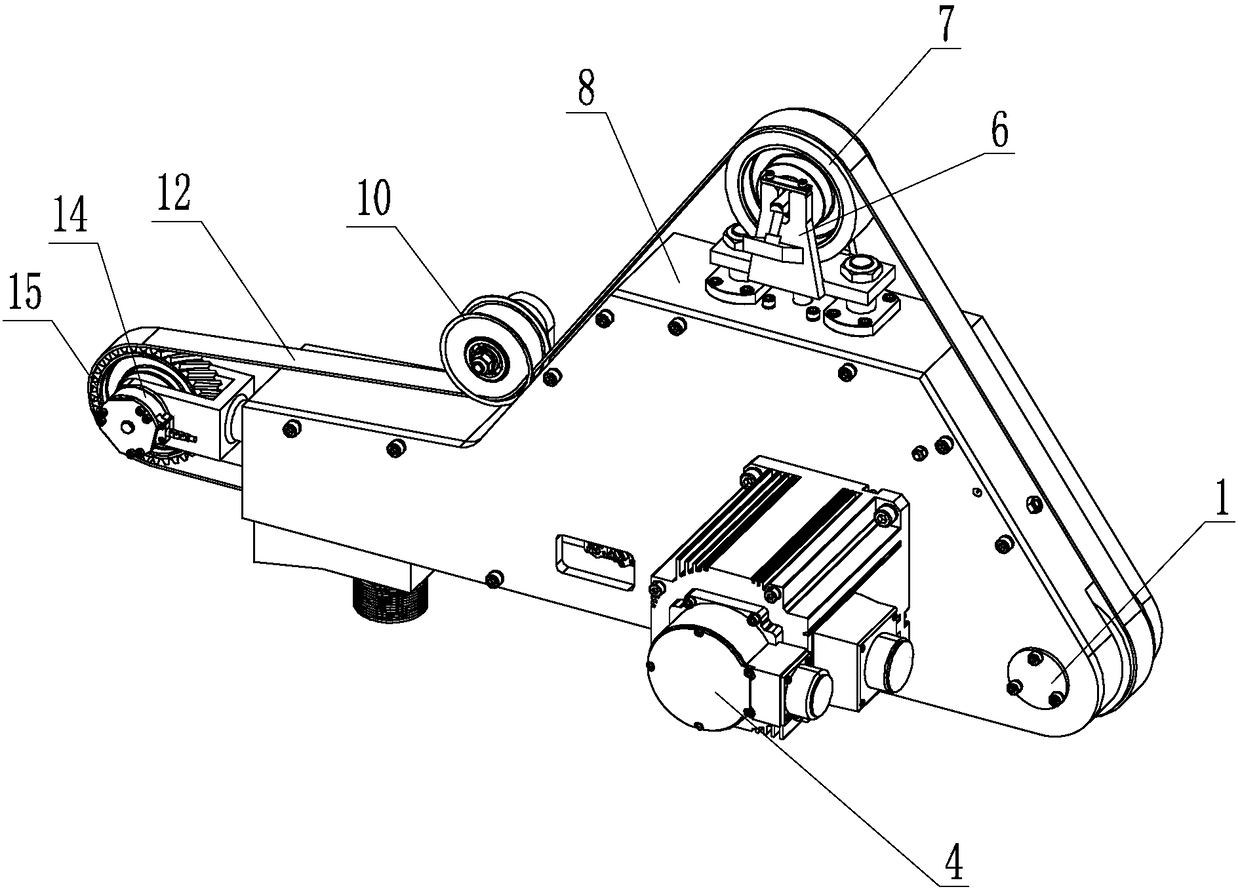
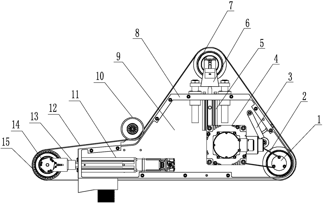
[0019] Specific implementation mode one: as Figure 1~3 As shown, the abrasive belt grinding tool installed at the end of the robot in this embodiment includes a drive wheel 1, a synchronous belt 2, a servo motor 4, a low-friction cylinder 5, a tensioner bracket 6, a tensioner 7, a frame 8, and a motor support Plate 9, transition wheel 10, servo electric cylinder 11, abrasive belt 12, contact wheel bracket 13, high-precision sensor 14 and contact wheel 15; tensioner 7 is installed on the upper end surface of frame 8 through tensioner bracket 6, low The friction cylinder 5 is fixed on the frame 8 and is located under the tensioner bracket 6, the driving wheel 1 is installed on the bottom of the frame 8, the servo electric cylinder 11 is installed horizontally on the bottom of the frame 8, and the motor support plate 9 is fixed on the frame 8 On the front end face, the servo motor 4 is fixedly mounted on the motor support plate 9, the output shaft of the servo motor 4 is connect...
specific Embodiment approach 2
[0025] Specific implementation mode two: as figure 1 As shown, the two sides of the transition wheel 10 in this embodiment are provided with annular ribs. With such a design, the ribs on both sides of the transition wheel 10 can correct the deviation of the abrasive belt 12 to ensure that the abrasive belt 12 is covered on the contact wheel 15 . Other components and connections are the same as those in the first embodiment.
specific Embodiment approach 3
[0026] Specific implementation mode three: as figure 1 and figure 2 As shown, the contact wheel 15 in this embodiment is a cylindrical helical rubber wheel. With this design, the toothed rubber wheel can buffer the contact force between the contact wheel and the workpiece to be processed. Compared with the straight tooth structure, the helical tooth structure is easier to form a uniform contact force. At the same time, the design of this rubber wheel increases the friction between the contact wheel and the abrasive belt. force to prevent the abrasive belt from slipping on the contact wheel. Other compositions and connections are the same as those in Embodiment 1 or 2.
PUM
 Abstract
Description
Claims
Application Information