
Rolling, cutting and lapping device for wood fibers

A lapping device, wood fiber technology, applied in wood processing equipment, bark area/debris/dust/waste removal, manufacturing tools, etc., can solve the problems of workers' health hazards, environmental pollution, etc., and achieve simple structure , the effect of convenient operation

Inactive Publication Date: 2018-08-24
王立
View PDF0 Cites 0 Cited by
  • Summary
  • Abstract
  • Description
  • Claims
  • Application Information

AI Technical Summary

Problems solved by technology

[0002] Lignocellulosic fiber is an organic flocculent fibrous substance obtained from natural renewable wood through chemical treatment and mechanical processing. It is widely used in concrete mortar, gypsum products, wood pulp sponge, asphalt roads and other fields. , it is often necessary to carry out milling work on wood fibers. At present, the milling work is usually carried out by the staff with a hand-held milling machine. During work, it is easy to generate a large amount of dust. Therefore, it causes great pollution to the environment, and it is harmful to the staff Health also can cause great harm, therefore, be badly in need of a kind of wood fiber milling and lapping device

Method used


Image

  • Rolling, cutting and lapping device for wood fibers
  • Rolling, cutting and lapping device for wood fibers
  • Rolling, cutting and lapping device for wood fibers

Examples


Embodiment Construction

[0014] Combine below Figure 1-4 The present invention will be described in detail.

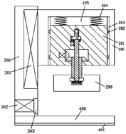
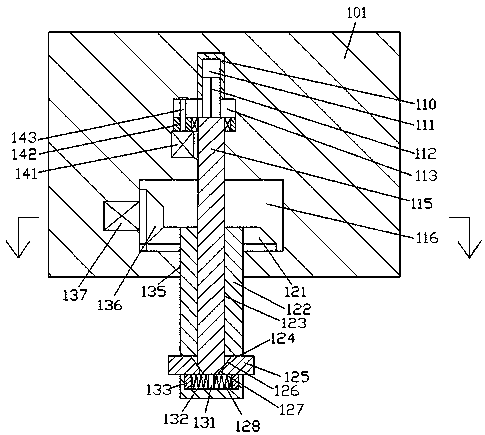
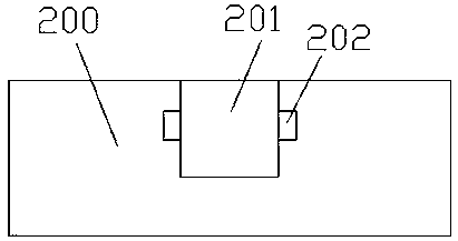
[0015] refer to Figure 1-4 , according to an embodiment of the present invention, a wood fiber milling and lapping device includes a support frame 300 fixedly installed on the bottom frame 400 and an installation main body 100 installed on the right end surface of the support frame 300 through a landing gear 301 The bottom end surface of the bottom frame 400 is fitted with a shockproof pad 401, and the bottom end surface of the installation main body 100 is provided with a slowing cavity 105, and a rolling body 101 is installed in the slowing cavity 105 for sliding fit. The top of the cutting main body 100 is symmetrically fixed with an elastic member 104, the top of the elastic member 104 is fixedly connected with the inner bottom wall of the slowing chamber 105, and the inner wall of the milling main body 101 is provided with a transfer chamber 116, and the transfer chamber 116 is provid...


PUM


Abstract

The invention discloses a rolling, cutting and lapping device. The device comprises a supporting frame which is fixedly mounted on a bottom frame, and an assembling body which is mounted on the rightside end surface of the supporting frame through a lifting device, wherein a damping protection cushion is closely arranged on the bottom end surface of the bottom frame; a slowing chamber is formed in the bottom end surface of the assembling body, and a rolling and cutting body is mounted in the slowing chamber in a sliding fitting manner; elastic parts are fixedly symmetrically arranged at the left and right of the top end of the rolling and cutting body; the top ends of the elastic parts are fixedly connected to the inner bottom walls of the releasing chamber; a transferring chamber is formed in the inner wall body of the rolling and cutting body; a guiding moving chamber is formed in the upper side of the transferring chamber; a rotating chamber is formed in the inner bottom wall of the transferring chamber in a mutual communication manner, and the rotating chamber passes through the bottom end surface of the rolling and cutting body; a rotating column is arranged in the rotating chamber in a rotating fitting manner, and the bottom end extending section of the rotating column passes through the bottom end surface of the rolling and cutting body and is equipped with a rolling and cutting plate in a fitting manner.

Description

technical field [0001] The invention relates to the technical field of wood fiber processing, in particular to a wood fiber milling and lapping device. Background technique [0002] Lignocellulosic fiber is an organic flocculent fibrous substance obtained from natural renewable wood through chemical treatment and mechanical processing. It is widely used in concrete mortar, gypsum products, wood pulp sponge, asphalt roads and other fields. , it is often necessary to carry out milling work on wood fibers. At present, the milling work is usually carried out by the staff with a hand-held milling machine. During work, it is easy to generate a large amount of dust. Therefore, it causes great pollution to the environment, and it is harmful to the staff Health also can cause great harm, therefore, be badly in need of a kind of wood fiber milling and lapping device. Contents of the invention [0003] The object of the present invention is to provide a wood fiber milling and lappin...

Claims


Application Information

Patent Timeline
Patent Type & Authority Applications(China)
IPC IPC(8): B27L11/08B27G3/00
CPCB27L11/08B27G3/00
Inventor 王立
Owner 王立
Learn More