Wax-polishing machine with micro-vibration mode

A technology of micro-vibration and mode, which is applied in vehicle maintenance, vehicle maintenance/repair, transportation and packaging, etc. It can solve the problems of poor waxing effect and achieve the effect of solving poor waxing effect and difficult operation

Pending Publication Date: 2018-08-24
王向东
View PDF2 Cites 0 Cited by
  • Summary
  • Abstract
  • Description
  • Claims
  • Application Information

AI Technical Summary

Problems solved by technology

In the actual use of this tech...

Method used


Image

  • Wax-polishing machine with micro-vibration mode
  • Wax-polishing machine with micro-vibration mode
  • Wax-polishing machine with micro-vibration mode

Examples


Embodiment 1

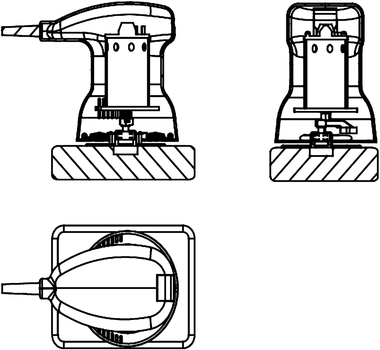
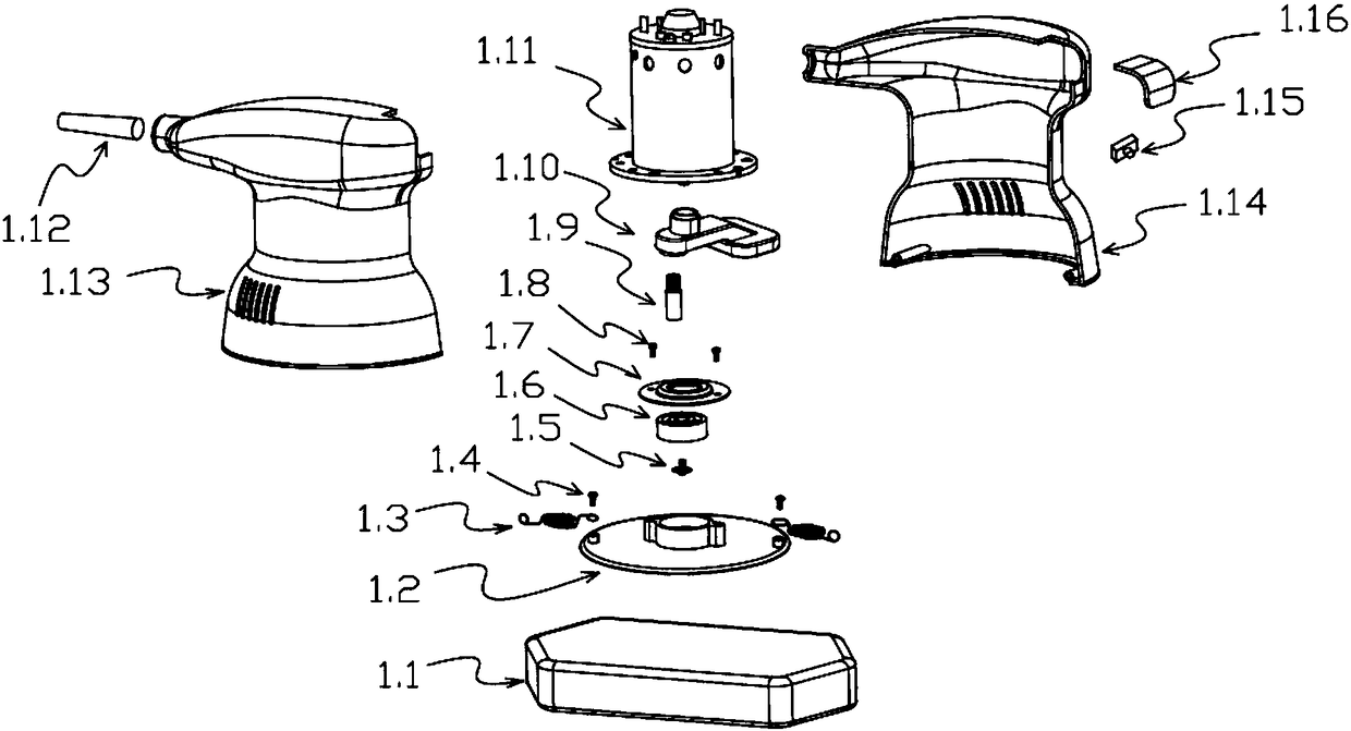
[0031] Example 1 (combined figure 1 and figure 2 describe):

[0032] For the single-head waxing machine, the output shaft of the motor 1.11 is fixed as a whole with the threaded hole at the upper end of the eccentric block 1.10 by means of threaded connection, so the eccentric block 1.10 and the motor 1.11 together with the motor 1.11 to make a circular motion along the axis of the main shaft of the motor. On the other hand, the threaded hole at the lower part of the eccentric block and the stub shaft 1.9 on the vibrating plate 1.2 are fixed as a whole by means of threaded connection; while the stub shaft 1.9 and the inner ring of the bearing 1.6 are fixed as a whole by the set screw 1.5, so that The eccentric block 1.10, the stub shaft 1.9 and the bearing 1.6 are regarded as a rigid assembly A with the motor, and this assembly A rotates at high speed with the rotation of the main shaft of the motor.

[0033] Waxing disc 1.1 is directly connected with vibrating disc 1.2 by ...

Embodiment 2

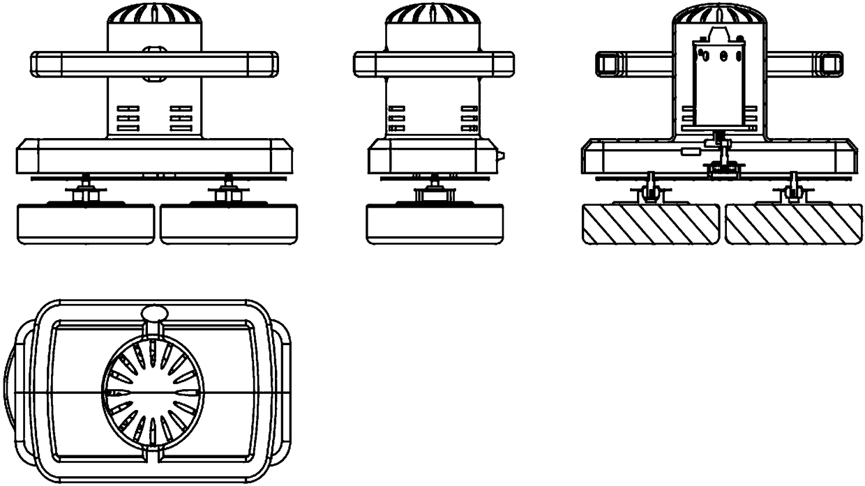
[0037] Example 2 (combined image 3 and Figure 4 describe):

[0038] The sub-waxing disc 2.17 of the multi-head waxing machine (referring to two or more waxing discs) is directly connected to the vibrating disc 2.8 by means of pasting, or through the sub-waxing disc group 2.11~2.16 and vibration. The discs 2.8 are connected by fasteners. The structural design of directly pasting the multi-head waxing disc to the vibrating disc is the same as that of the single-head waxing machine, and will not be repeated here. In the following, only the focus of the sub-waxed disk structure mode will be described in detail.

[0039] The output shaft of the DC motor 2.2 on the multi-head waxing machine is fixed as a whole with the threaded hole at the upper end of the eccentric block 2.3 by means of threaded connection, so the eccentric block 2.3 is together with the motor 2.2. On the other hand, the threaded hole at the lower part of the eccentric block 2.3 and the stub shaft 2.4 on the ...


PUM


Abstract

A wax-polishing machine with a micro-vibration mode disclosed by the invention consists of an outer case group, a power assembly, a vibration assembly and a waxing assembly, wherein the outer case group comprises a left outer case, a right outer case, a handle and a connecting plate; the power assembly comprises a direct current (DC) permanent magnet motor, a rectifier bridge and a power cord; thevibration assembly comprises an eccentric block, a vibration plate and dampers; the waxing assembly comprises a waxing plate and a waxing plate base; the alternating current (AC) of an external AC power source is converted into the DC permanent magnet motor through the power cord and the rectifier bridge; the eccentric block is fixed on the main shaft of the DC permanent magnet motor; the eccentric block performs a circular motion of the same rotational speed along with the DC permanent magnet motor; and the dampers are mounted between the vibration plate and the left outer case and between the vibration plate and the right outer case. The wax-polishing machine with the micro-vibration mode eliminates the inertia rotation of the waxing plate through the resistance generated by damping components, and transmits the deflection generated by the eccentric block to the waxing plate, so that the waxing plate only produces the micro-vibration mode in the circumferential direction and eliminates a self-rotation mode.

Description

technical field [0001] The invention belongs to an existing automobile waxing machine, in particular to a micro-vibration mode waxing machine. Background technique [0002] Existing automotive waxing machines all use one or more waxing discs to perform surface processing on the automotive shell bowl, such as scratch removal, waxing and polishing, through direct drive or rotational motion generated by inertial force. [0003] When using the waxing machine, the operator often encounters difficulty in control. This is because the rotating waxing disc will deflect in a single direction, and the operator needs to firmly hold the waxing machine with both hands to prevent the waxing The wax machine is out of control, which is not only easy to cause fatigue; on the other hand, during the waxing operation, it is necessary to maintain a good waxing posture while controlling the waxing disc to not deviate from the predetermined waxing trajectory due to centrifugal force, which will gre...

Claims


Application Information

Patent Timeline
IPC IPC(8): B60S5/00
CPCB60S5/00
Inventor 王向东
Owner 王向东
Why Eureka
Try Eureka