Compaction embroidering system for honeycomb porous-structure cotton and use method thereof

A technology of porous structure and honeycomb, which is applied in needle looms, non-woven fabrics, textiles and papermaking, etc. It can solve the problems of finishing and compacting textiles, achieve good results, improve compacting effects, and facilitate weaving.

Active Publication Date: 2018-08-24
平邑仁安中医药产业发展有限公司
View PDF7 Cites 1 Cited by
  • Summary
  • Abstract
  • Description
  • Claims
  • Application Information

AI Technical Summary

Problems solved by technology

[0004] The purpose of the present invention is to overcome the defects and problems existing in the prior art that cannot arrange and compact thicker and fluffier textiles, and provide a method that can arrange and compact thicker and fluffier textiles. The compacting barbed weaving system of honeycomb porous structure cotton and using method thereof

Method used


Image

  • Compaction embroidering system for honeycomb porous-structure cotton and use method thereof
  • Compaction embroidering system for honeycomb porous-structure cotton and use method thereof
  • Compaction embroidering system for honeycomb porous-structure cotton and use method thereof

Examples


Embodiment 1

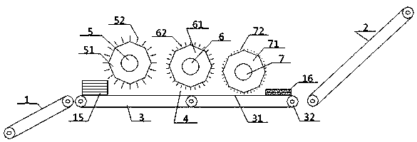
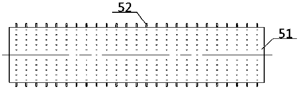
[0052] see Figure 1 to Figure 7 , a compacting and weaving system for cotton with a honeycomb porous structure, including a main conveying device 3 and a finishing device 4, the main conveying device 3 includes a main conveying belt 31 and a main conveying roller 32 connected to each other, and the main conveying belt 31 The finishing device 4 is arranged directly above the middle part; the finishing device 4 includes a No. 1 licker-in roller 5, a No. 2 licker-in roller 6, and a No. Licker-in 5, No. 2 licker-in 6, and No. 3 licker-in 7 are all located directly above the main conveyor belt 31; the No. 1 licker-in 5 includes a No. 1 roller body 51 and a plurality of No. 1 licker-in rollers uniformly arranged along its side circumference. Needles 52, the No. 2 licker-in roller 6 includes a No. 2 roller body 61 and a plurality of No. 2 licker-in needles 62 uniformly arranged along its side circumference, and the No. 3 licker-in roller 7 includes a No. 3 roller body 71 and a numbe...

Embodiment 2

[0055] Basic content is the same as embodiment 1, the difference is:

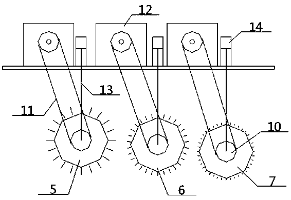
[0056] The ends of the No. 1 roller body 51, the No. 2 roller body 61, and the No. 3 roller body 71 are all provided with a rotary drive shaft 10, and the outer side of the rotary drive shaft 10 is surrounded by the output of the rotary transmission belt 11 and the rotary drive motor 12. end carries out transmission fit, and the center position of rotating drive shaft 10 is connected with the output end of lifting motor 14 by lifting rope 13.

[0057] In the process of conveying and passing by, carry out any one or all of the following operations: the first: change the rotation direction of the No. 1 roller body 51, the No. 2 roller body 61, and the No. 3 roller body 71 by rotating the transmission belt 11 Or rotation speed or change simultaneously; The second kind: change the height of No. 1 roller body 51, No. 2 roller body 61, and No. 3 roller body 71 by hoisting rope 13.

Embodiment 3

[0059] Basic content is the same as embodiment 1, the difference is:

[0060] The distribution density of the No. 1 needle 52 on the side circumference of the No. 1 roller body 51 is smaller than the distribution density of the No. 2 needle 62 on the side circumference of the No. 2 roller body 61, and the distribution density of the No. 2 needle 62 on the side circumference of the No. The distribution density is smaller than the distribution density of No. 3 needles 72 on the side circumference of No. 3 roller body 71 . The length of the first needle 52 is greater than that of the second needle 62 , and the length of the second needle 62 is greater than the length of the third needle 72 .


PUM


Abstract

The invention provides a compaction embroidering system for honeycomb porous-structure cotton. According to the system, a finishing device in the system comprises a first embroidering roller, a secondembroidering roller and a third embroidering roller which are arranged in sequence along the transportation direction of a main transportation belt, the three embroidering rollers are all located directly above the main transportation belt, each embroidering roller comprises a roller body and a plurality of embroidering needles evenly arranged around the side wall of the corresponding roller body, the lengths of embroidering needles of the three embroidering rollers are shortened in sequence, the distributed densities of the embroidering needles of the three embroidering rollers are increasedin sequence, the distances between the three embroidering rollers and the main transportation belt are reduced in sequence, the end portions of the roller bodies are provided with rotating driving shafts, the outer side walls of the rotating driving shafts are in transmission cooperation with output ends of rotating driving motors through rotating transmission belts, and the central positions ofthe rotating driving shafts are connected with output ends of lifting motors through lifting ropes. The compaction embroidering system for honeycomb porous-structure cotton have the advantages that not only can thicker and fluffier textile bodies be finished and compacted to provide convenience for the weaving and crossing of the fibers in the textile bodies, but also the sticking efficiency and pulling efficiency are higher, the adjustability is higher, and the application range is wider.

Description

technical field [0001] The invention relates to a finishing device for textiles, which belongs to the field of textiles, in particular to a compacting and weaving system for cotton with a honeycomb porous structure and its use method, and is particularly suitable for finishing and pressing thicker and fluffier textiles Reality. Background technique [0002] At present, the production equipment of a complete set of textile products mainly includes an opening machine, a carding machine, a web-laying machine and a needle punching machine. The textile fiber is opened by the opening machine and transported to the carding machine, and then the textile fiber is carded by the carding machine. And the carded textile fibers are sent to the web-laying machine to lay the net, and the web-laying machine is sent to the needle punching machine or other subsequent processing equipment after laying the net. However, when making a multi-layered textile body, the initial The thickness of the ...

Claims


Application Information

Patent Timeline
Patent Type & Authority Applications(China)
IPC IPC(8): D04H18/02
CPCD04H18/02
Inventor 张智明段耀帅卢宾宾姬巧玲徐巧梅顺齐肖人彬
Owner 平邑仁安中医药产业发展有限公司
Why Eureka
Try Eureka