Permanent magnet type magnetic bearing pair

A magnetic suspension bearing and permanent magnet technology, applied in the field of bearings, can solve the problems of large frictional resistance, short service life and high repair rate, and achieve the effects of increasing bearing load, long service life and low use cost

Inactive Publication Date: 2018-08-24
SHANDONG FENGGANG MACHINERY EQUIP
View PDF9 Cites 1 Cited by
  • Summary
  • Abstract
  • Description
  • Claims
  • Application Information

AI Technical Summary

Problems solved by technology

[0002] The existing various types of sliding bearings and rolling bearings have sliding or rolling direct contact between their corresponding moving parts, which have the advantages of strong bearing capacity and high position accuracy, but due to mutual contact, frictional resistance is large, and mechanical wear is easy to occur and heat generation, mechanical vibration and noise, generally require the use of lubricants, high operating costs, high repair rate, and short service life

Method used


Image

  • Permanent magnet type magnetic bearing pair
  • Permanent magnet type magnetic bearing pair
  • Permanent magnet type magnetic bearing pair

Examples


Embodiment 1

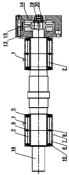
[0044] Such as figure 1 Shown: in this embodiment, an axial bearing is installed on the right end of the shaft 18, a radial bearing is installed on the right end and the left end of the shaft 18, and the radial bearing positioned at the right end of the shaft 18 is arranged on the left side of the axial bearing.

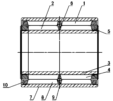
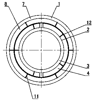
[0045] Such as Figure 2~3As shown: the radial bearing includes an outer ring assembly 1 and an inner ring assembly 2 arranged coaxially. The outer ring assembly 1 includes an outer ring 7 and an annular outer ring magnetic steel 8 coaxially arranged in the outer ring 7. The ring magnet 8 is connected with the outer ring 7, the inner ring assembly 2 includes the inner ring 3 and the annular inner ring magnet 4 coaxially arranged outside the inner ring 3, the inner ring magnet 4 is connected with the inner ring 3, and the inner ring The magnet 4 is coaxially arranged in the outer magnet 8 and rotated with the outer magnet 8; the inner magnet 4 and the outer magnet 8 ...

Embodiment 2

[0077] Such as Figure 11 As shown: the difference between embodiment 2 and embodiment 1 is that in this embodiment, two thrust plates 15 are arranged at intervals, and a thrust plate 22 is respectively arranged on the middle and both sides of the two thrust plates 15, and the thrust plates 22 is coaxially installed in the housing 21, the housing 21 is a cylinder arranged horizontally, and both ends of the housing 21 are open. The side portion of the thrust plate 22 is fixedly connected to the inner wall of the housing 21 , and the side portion of the thrust plate 15 is spaced apart from the adjacent thrust plate 22 .

[0078] The right side of the thrust plate 22 on the left side, the left side of the thrust plate 22 on the right side, and both sides of the thrust plate 22 in the middle are all embedded with fixed magnets 16, and both sides of each thrust plate 15 are provided with There are rotating magnets 17, and the rotating magnets 17 and the adjacent fixed magnets 16 a...

Embodiment 3

[0083] Such as Figure 12 As shown: the difference between Embodiment 3 and Embodiment 1 is that a radial bearing is set in the middle of the shaft 18, and an axial bearing is installed at both ends of the shaft 18, and the thrust plates 22 of the two axial bearings pass through The housing 21 is fixedly connected.

[0084] In this embodiment, each axial bearing only includes one thrust plate 22 and one thrust plate 15 , and the thrust plate 15 is arranged outside the corresponding thrust plate 22 . The inner side of the thrust plate 15 is provided with a rotating magnet 17 , and the outer side of the thrust plate 22 is provided with a fixed magnet 16 . The thrust plates 22 of the two axial bearings are fixedly connected with the housing 21 , and the outer ring 7 of the radial bearing is also fixedly connected with the housing 21 . The axial bearing at the left end bears the axial force to the right, and the axial bearing at the right end bears the axial force to the left. ...


PUM


Abstract

The invention belongs to the technical field of bearings and discloses a permanent magnet type magnetic bearing pair. The permanent magnet type magnetic bearing pair is characterized in that an innerring (3) of a radial bearing sleeves a shaft (18), outer ring magnetic steel (8) is coaxially mounted on the inner wall of an outer ring (7), inner ring magnetic steel (4) is coaxially mounted on theouter wall of the inner ring (3), and the outer wall of the inner ring magnetic steel (4) and the inner wall of the outer ring magnetic steel (8) are identical in magnetic polarity. One side, close toa thrust collar (22) of a thrust disc (15) of an axial bearing is provided with annular rotating magnetic steel (17). One side, close to the thrust disc (15), of the thrust collar (22) is provided with annular fixed magnetic steel (16). Adjacent sides of the rotating magnetic steel (17) and the fixed magnetic steel (16) are identical in magnetic polarity. The permanent magnet type magnetic bearing pair is free of noise and heat generation, lubrication in a utilization process is avoided, long service life is realized, and bearing of both radial force generated by a radial load and axial forcegenerated by an axial load can be realized.

Description

technical field [0001] The utility model relates to a permanent magnet type magnetic suspension bearing pair, which belongs to the technical field of bearings. Background technique [0002] The existing various types of sliding bearings and rolling bearings have sliding or rolling direct contact between their corresponding moving parts, which have the advantages of strong bearing capacity and high position accuracy, but due to mutual contact, frictional resistance is large, and mechanical wear is easy to occur And heat, there is mechanical vibration, there is noise, in general, lubricants are required, the operating cost is high, the repair rate is high, and the service life is short. Contents of the invention [0003] The technical problem to be solved by the present invention is: to overcome the deficiencies of the prior art, to provide a permanent magnetic magnetic suspension bearing that bears the axial force generated by the axial load and the radial force generated b...

Claims


Application Information

Patent Timeline
Patent Type & Authority Applications(China)
IPC IPC(8): F16C32/04
CPCF16C32/0406
Inventor 牛会柱陈玉福
Owner SHANDONG FENGGANG MACHINERY EQUIP
Why Eureka
Try Eureka