System standby capacity reducing transformer station optimization method for self-generation power plant enterprise

A technology of reserve capacity and optimization method, applied in the direction of electrical components, circuit devices, AC network circuits, etc., can solve the problems of low utilization rate of power enterprise equipment, burden of electric power enterprise grid construction, and increase investment of electric power enterprise, so as to improve the system Economic operation level, saving reserve capacity cost, and reducing the effect of reserve capacity

Inactive Publication Date: 2018-08-24
CHINA PETROCHEMICAL CORP
View PDF1 Cites 2 Cited by
  • Summary
  • Abstract
  • Description
  • Claims
  • Application Information

AI Technical Summary

Problems solved by technology

[0005] In order to ensure that enterprises can provide safe and reliable power supply when the output of self-provided power plants changes, power companies need to increase investment and increase the construction of spare capacity, which undoubtedly increases the construction cost; because self-provided power plants occupy additional reserve capacity and public resources , which caused the problem of low utilization rate of powe

Method used


Image

  • System standby capacity reducing transformer station optimization method for self-generation power plant enterprise
  • System standby capacity reducing transformer station optimization method for self-generation power plant enterprise
  • System standby capacity reducing transformer station optimization method for self-generation power plant enterprise

Examples


Example Embodiment

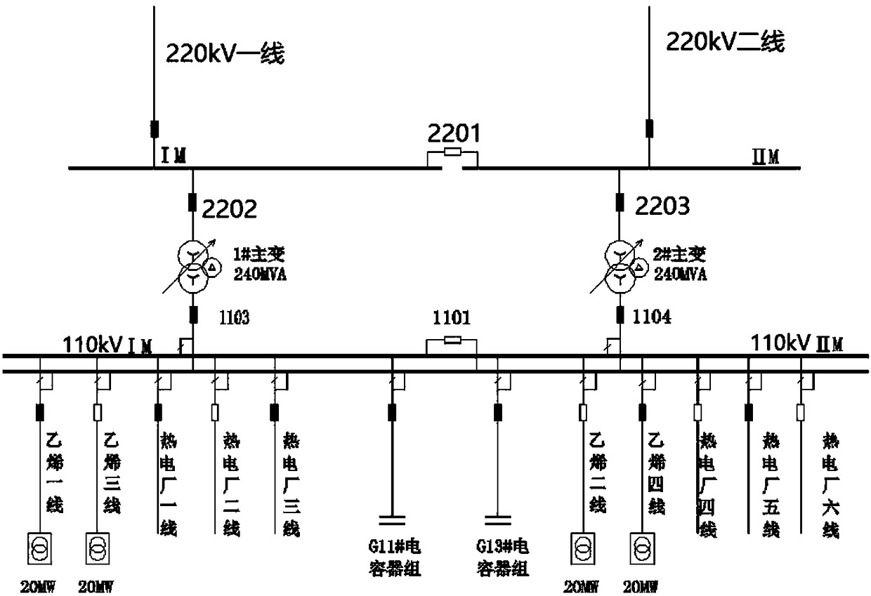
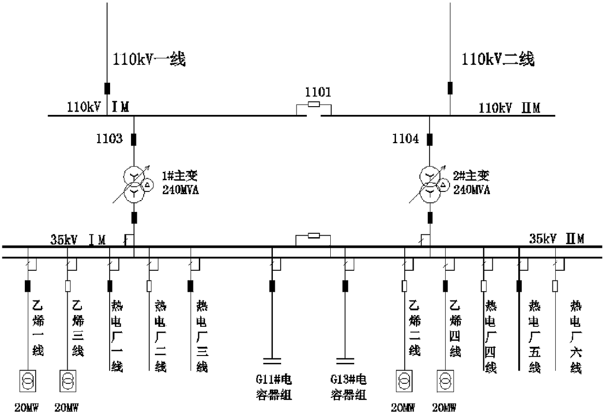
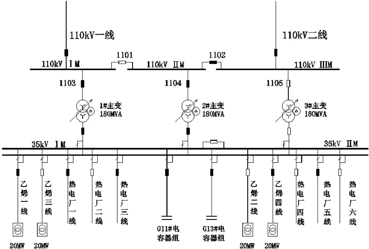
[0059] like Figure 1~6 Shown is a kind of self-provided power plant enterprise substation optimization method of the present invention that reduces system reserve capacity, specifically comprises the following steps:

[0060] Step 1. According to the capacity parameters of the enterprise's electrical equipment, determine the estimated maximum power supply load, the capacity and quantity of the generator set of the power plant to be built, and analyze the power balance of the enterprise, including the normal operation mode of the system and the N-1 operation mode. Power balance analysis, and then determine the construction capacity of the self-contained power plant to be built according to the power balance analysis results. The construction capacity of the self-provided power plant to be built includes the capacity of the power plant, the maximum output of the generator and the capacity of the main transformer. In this example, the power plant to be built is expected to have ...


PUM


Abstract

The invention discloses a system standby capacity reducing transformer station optimization method for self-generation power plant enterprise. The method comprises the steps that 1) the predicted maximal power supply load and the capacity and number of generators of a generator set of the self-generation power plant to be constructed are determined, electric quantity balancing analysis is carriedout on the enterprise, and the construction capacity of the self-generation power plant to be constructed is determined according to an electric quantity balancing analysis result; 2) a wiring schemeincluding three main transformers and three segments of buses is used, two main transformers operate, one main transformer is in a standby state, and basic electricity charge is collected according tothe total capacity of two main transformers; 3) the main transformation capacity of the transformer station is calculated in the N-1 operation mode, and the standby capacitor provided by a power gridsystem is obtained; 4) N-1 verification is carried out on the wiring scheme of the transformer station; and 5) an investment economic effect of the transformer station wring scheme is analyzed in a total own cost method. Thus, the cost of the standby capacity can be omitted, the system standby capacity can be reduced, and a win-win target is realized for a power enterprise and a self-generation power plant enterprise.

Description

technical field [0001] The invention relates to a technology for optimizing the wiring scheme of a power system substation, in particular to a method for optimizing a substation of a self-provided power plant enterprise for reducing system reserve capacity. Background technique [0002] In recent years, with the rapid development of my country's economy, the power load has risen sharply, resulting in a large-scale power shortage in various regions. According to the statistics of the National Energy Administration, in 2013, the electricity consumption of heavy industry accounted for 60.3% of the electricity consumption of the whole society, and the production process of these heavy industry enterprises is usually continuous, such as steel, aluminum factories, petroleum, chemical and other enterprises, these enterprises process All of them are flammable and explosive dangerous substances. If there is a sudden power failure, accidents such as sudden explosion or leakage are lik...

Claims


Application Information

Patent Timeline
IPC IPC(8): H02J3/00
CPCH02J3/00H02J2203/20
Inventor 唐海东程林李宏湘田浩邹国铖胡庭枝江明基高清茂钟兴
Owner CHINA PETROCHEMICAL CORP
Why Eureka
Try Eureka