A stator permanent magnet type dual-rotor magnetic field modulation motor and its design method

A technology of magnetic field modulation and design method, applied in the direction of magnetic circuit rotating parts, electromechanical devices, electrical components, etc., can solve the problems of rare earth permanent magnets easy to demagnetize at high temperature and poor heat dissipation conditions, so as to improve the weak magnetic performance and reduce the copper wire. The amount of usage and the effect of reducing torque ripple

Active Publication Date: 2020-07-31
JIANGSU UNIV
View PDF8 Cites 0 Cited by
  • Summary
  • Abstract
  • Description
  • Claims
  • Application Information

AI Technical Summary

Problems solved by technology

[0007] At this stage, rare earth permanent magnets with high magnetic energy product are prone to demagnetization at high temperatures. Due to the poor heat dissipation conditions of rotor permanent magnet motors, it is easier to cause high temperature conditions. Therefore, stator permanent magnet motors are more inclined to choose stator permanent magnet motors in the case of high-speed changes in the magnetic field; about Reduce the amount of rare earth permanent magnets and keep the performance of the motor at a high level, that is, there are still relatively few research patents on improving the utilization efficiency of the unit permanent magnet

Method used


Image

  • A stator permanent magnet type dual-rotor magnetic field modulation motor and its design method
  • A stator permanent magnet type dual-rotor magnetic field modulation motor and its design method
  • A stator permanent magnet type dual-rotor magnetic field modulation motor and its design method

Examples


Embodiment Construction

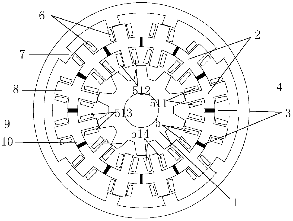
[0048] Such as figure 1 , a stator permanent magnet type dual-rotor magnetic field modulation motor of the present invention and a design method thereof, the motor includes an inner rotor 1, a stator 2 and an outer rotor 4 in sequence from the inside to the outside, between the inner rotor 1 and the stator 2, between the stator 2 and the Outer rotors 4 all leave air gaps. Each yoke of the stator 2 is embedded with a radial permanent magnet 3, which adopts tangential excitation, and the N poles and S poles of the radial permanent magnets 3 are arranged alternately along the circumference; the stator outer teeth 8, the stator inner teeth 9 It is a straight tooth structure, the inner winding 5 and the outer winding 6 are arranged in the slot of the stator 2, and the inner rotor 1 and the outer rotor 4 are both outer rotor teeth 7 and inner rotor teeth 10 of a salient pole tooth structure formed by lamination of silicon steel sheets. . In addition, the number of pole pairs of pe...


PUM

PropertyMeasurementUnit
polar arc coefficientaaaaaaaaaa

Abstract

The invention discloses a stator permanent magnet type double-rotor magnetic field modulation motor and a design method thereof. The stator permanent magnet type double-rotor magnetic field modulationmotor comprises a stator, an inner rotor and an outer rotor. The stator is arranged between the two rotors. Permanent magnets are embedded in the yoke part of the stator in the radial manner. The magnetizing direction of the permanent magnets is tangential to the circumference, and the N poles and the S poles of the permanent magnets are alternately arranged. The difference between the positionsof the inner rotor and the outer rotor is half of the polar distance of the two rotors, while the rotating directions and the rotating speeds of the two rotors are the same. The armature winding of the motor adopts the concentrated winding mode. According to the invention, two motors with double salient pole structures are combined, and the magnetic chains of the same phase coil are complementary.The single-coil magnetic chain of the motor is unipolar, and the magnetic chain of the synthetic winding is bipolar. The structure of the motor has the magnetic field modulation effect, so that the motor has higher counter electromotive force and torque performance compared with a conventional salient pole structure motor. After the armature is loaded, the generated armature magnetic field does not pass through the permanent magnet. Therefore, the permanent magnet is prevented from demagnetizing due to over-large current. The rotors of the motor are formed by laminating silicon steel sheets with salient pole structures only, so that the good robustness is achieved.

Description

technical field [0001] The invention relates to a double-rotor motor, a magnetic field modulation motor and a stator permanent magnet motor. It is suitable for applications that require high motor volume and torque capacity, such as: electric vehicles, aerospace, etc. Background technique [0002] With the development of science and technology, many occasions at this stage need to be driven by motors with small volume but high torque. The rare earth permanent magnets used in permanent magnet motors at this stage have high magnetic energy products and can generate high magnetic flux in the air gap. Therefore, compared with the electric excitation motor, it has a more compact structure and a higher torque density. In the permanent magnet motor, according to the different arrangement positions of the permanent magnets, it can be divided into rotor permanent magnet motor, stator permanent magnet motor and stator permanent magnet motor. [0003] China Invention Patent Applicati...

Claims


Application Information

Patent Timeline
Patent Type & Authority Patents(China)
IPC IPC(8): H02K16/02H02K1/24H02K1/17H02K3/04
CPCH02K1/17H02K1/24H02K3/04H02K16/02H02K2213/03
Inventor 赵文祥朱旭辉吉敬华朱剑姚甜赵美玲
Owner JIANGSU UNIV
Why Eureka
Try Eureka