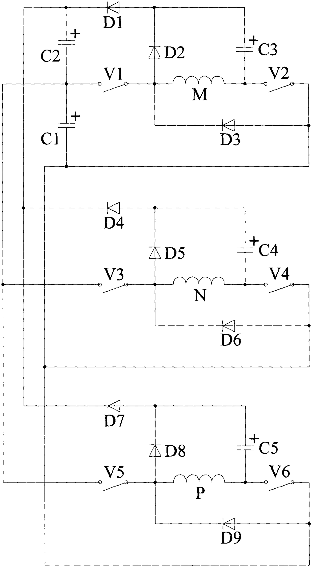
Converter system of switch reluctance motor

A technology of switched reluctance motor and converter system is applied in the direction of controlling generators, control systems, and generators through magnetic field changes, which can solve the problems of increasing system control complexity, increasing system losses, increasing costs, and the like. Achieve the effect of facilitating maximum power output tracking, reducing torque ripple, and enhancing flexibility

Inactive Publication Date: 2018-08-24
CHINA JILIANG UNIV
View PDF7 Cites 2 Cited by
  • Summary
  • Abstract
  • Description
  • Claims
  • Application Information

AI Technical Summary

Problems solved by technology

[0005] The excitation and power generation of the switched reluctance generator must be realized around the operation control of the inverter circuit connected to its winding. Without the winding inverter circuit, the switched reluctance generator naturally has no meaning; Position regulation and different phase windings are energized and excited, so the converter is also indispensable; at present, in some power generation / electric four-quadrant hybrid systems using switched reluctance motors, the electric operation converter and the power generation operation converter They are often separated, and each adopts its own converter system, which will inevitably increase the structural complexity and control complexity of the converter system, and also increase the cost. High reliability, integrated switched reluctance generator / motor converter system is what the industry needs
[0006] When the switched reluctance motor operates as a generator, the existing inverter system, in the excitation stage, most of the excitation power supply has realized the self-excitation mode, but many new self-excitation power supplies have a complicated structure and need to be equipped with a special excitation inverter circuit system, and A separate control system also increases the control complexity of the system
[0007] In practice, the DC voltage generated by the switched reluctance generator often requires a higher voltage value. In addition to taking certain measures to boost the voltage, if the DC voltage at the output terminal of the switched reluctance motor converter itself is too low, it will inevitably increase the subsequent voltage. The boost pressure, even needs several stages of boost, which increases the system loss

Method used


Image

  • Converter system of switch reluctance motor

Examples


Embodiment Construction

[0033] The switched reluctance motor in this embodiment has three-phase windings, which are M / N / P three-phase windings according to the order distributed on the stator. Each phase winding is composed of two branch windings and is symmetrically wound on different salient poles of the stator. above, that is, the six salient poles of the stator, as attached figure 1 Shown is the main converter circuit of the three-phase winding switched reluctance motor of this embodiment.

[0034]The switched reluctance motor converter system consists of a first capacitor C1, a second capacitor C2, a third capacitor C3, a fourth capacitor C4, a fifth capacitor C5, a first switch V1, a second switch V2, a third switch The tube V3, the fourth switch tube V4, the fifth switch tube V5, the sixth switch tube V6, the first diode D1, the second diode D2, the third diode D3, the fourth diode D4, the Fifth diode D5, sixth diode D6, seventh diode D7, eighth diode D8, ninth diode D9, first phase winding M...


PUM


Abstract

Disclosed is a converter system of a switch reluctance motor. When the switch reluctance motor is used as a generator for operation, a first capacitor is used as an exciting power supply; charging ofthe first capacitor can be realized in the power generation stage; by adjusting the duty ratio of a first switching tube, the power generation voltage value can be adjusted flexibly to satisfy requirement of the system; when the switch reluctance motor is used as a motor for operation, the same set of current conversion circuit is adopted, and energy regeneration capability is also achieved; and the whole system is simple in structure, low in cost, high in reliability, and can be applicable to medium and small-sized switch reluctance generator application systems and driving systems under various loads.

Description

technical field [0001] The invention relates to the field of switched reluctance motor systems, in particular to a multifunctional low-power switched reluctance motor converter system and a control method thereof. Background technique [0002] The switched reluctance motor has a simple and solid structure, low manufacturing cost, no windings on the rotor, no permanent magnets, high reliability, and the failure of one phase winding does not affect the normal operation of the other phase windings. It has strong fault tolerance and has broad application prospects. [0003] In theory, switched reluctance motors can be used as motors or as generators; as generators, since DC transmission has been increasingly valued by the power sector in recent years, local DC power grids have begun to take shape in some places. As a result, more and more load devices are directly powered by DC power supply, and the switched reluctance generator directly outputs DC power. [0004] Switched relu...

Claims


Application Information

Patent Timeline
Patent Type & Authority Applications(China)
IPC IPC(8): H02P9/00H02P9/30
CPCH02P9/008H02P9/305
Inventor 孙冠群宋春伟郭倩
Owner CHINA JILIANG UNIV
Why Eureka
Try Eureka