
Low-resistance and efficient fluidization demister device and demisting method thereof

A low-resistance, high-efficiency, mist eliminator technology, applied in chemical instruments and methods, separation methods, dispersed particle separation, etc. Improve convenience, high demisting efficiency and low cost

Pending Publication Date: 2018-08-28
WUHAN UNIV OF SCI & TECH
View PDF10 Cites 2 Cited by
  • Summary
  • Abstract
  • Description
  • Claims
  • Application Information

AI Technical Summary

Problems solved by technology

[0003] Although the running resistance of the baffle plate demister is low, its demisting effect is difficult to meet the requirements; the swirl plate separator or cyclone demister has high demisting efficiency and large processing capacity, but the running resistance is large; Although demisters and fiber demisters have high demisting efficiency, they are easy to block and have a short service life; although electrostatic demisters have good demisting effects, their investment and operating costs are high

Method used


Image

  • Low-resistance and efficient fluidization demister device and demisting method thereof
  • Low-resistance and efficient fluidization demister device and demisting method thereof
  • Low-resistance and efficient fluidization demister device and demisting method thereof

Examples


Embodiment 1

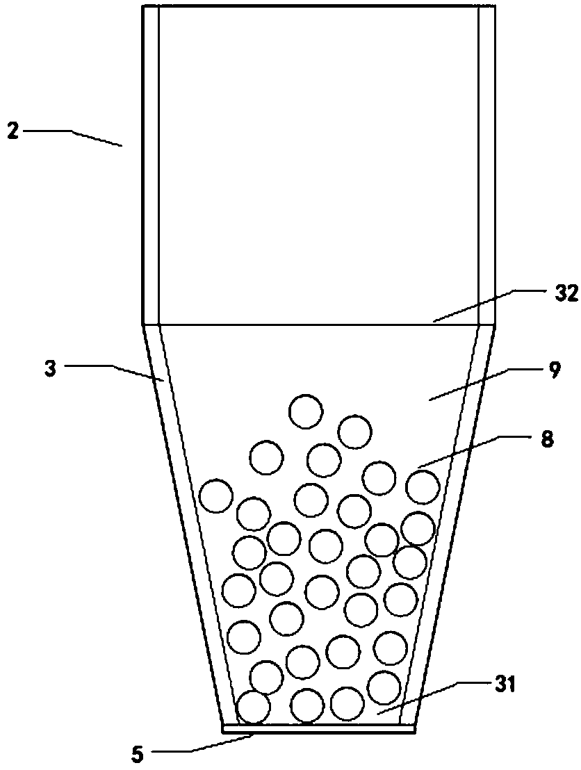
[0038] Example 1 as image 3 As shown, the present invention is a low-resistance and high-efficiency fluidized demister. The gas to be treated is introduced from one end of the vertically installed fluidized demister and discharged from the other end. The fluidized demister includes a variable-diameter pipe 3 , the sieve plate 5 arranged at the bottom of the variable diameter pipeline, the demister chamber 9 enclosed between the sieve plate and the variable diameter pipeline, and the demister medium 8 placed in the demist chamber, the variable diameter pipeline inlet 31 The area is smaller than that of the outlet 32. The inlet of the variable-diameter pipe faces downward for introducing the gas to be treated, and the outlet of the variable-diameter pipe upwards for discharging the purified gas. The gas to be treated contains atomized liquid and / or solid particles.

[0039] The outlet area at the upper end of the variable-diameter pipe is 1.1 to 8 times that of the inlet at the...

Embodiment 2

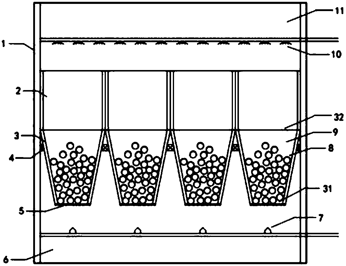
[0046] Example 2, such as figure 1 As shown in the low-resistance and high-efficiency demister of the fluidized demister, at least one of the fluidized demisters is installed in the hole of the flower plate 4 in the confined space 1, and the flower plate is a common one in the bag filter. The partitions with through holes of the same size are distributed, and the fluidized mist eliminator and the flower plate together divide the closed space into a clean air chamber 11 and a mist chamber 6, and the clean air chamber is located above the outlet of each fluidized mist eliminator. Extension cylinder 2, the height of the extension cylinder is greater than the distance that the demisting medium moves upward against gravity, and is used to prevent the demisting medium from running away. The cleaning nozzle 10 connected to the liquid pipe is arranged above the extension cylinder 2 for cleaning the demisting medium In the mist chamber, the gas nozzle 7 connected with the compressed ga...

Embodiment 3

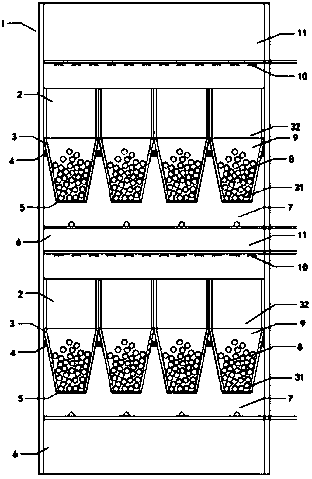
[0058] Example 3, such as figure 2 As shown in the low-resistance and high-efficiency fluidized mist eliminator, at least one of the fluidized mist eliminators is installed in the hole of the flower plate 4 in the enclosed space 1, and the fluidized mist eliminator and the flower plate together make the enclosed space It is divided into a clean air chamber 11 and a mist chamber 6. In the clean air chamber, an extension tube 2 is connected above the outlet of each fluidized demister, and a cleaning nozzle 10 connected to a liquid pipe is arranged above the extension tube 2 for cleaning and demistering. Fog medium: The gas nozzle 7 connected to the compressed gas pipe is arranged below the inlet of each fluidized mist eliminator in the mist chamber for pre-fluidizing the mist eliminator.

[0059] The aforementioned low-resistance and high-efficiency fluidized demister adopts multiple low-resistance and high-efficiency fluidized demisters for demisting in series, and can also us...


PUM

PropertyMeasurementUnit
Diameteraaaaaaaaaa
Resistanceaaaaaaaaaa

Abstract

The invention discloses a low-resistance and efficient fluidization demister device and a demisting method thereof. A fluidization demister adopts a diameter-variable pipeline with a large top and a small bottom, wherein the diameter-variable pipeline is internally provided with a demisting cavity; airflow enters from the bottom of the diameter-variable pipeline and a demisting medium in the demisting cavity has a fluidized state under the action of the ascending airflow; meanwhile, the ascending airflow meets the demisting medium with the fluidized state; the direction of the airflow is deviated under the action of inertia, baffling and the like; liquid drops and solid grains in the airflow are continuously adsorbed, coagulated and intercepted by the spherical demisting medium; the airflow which is subjected to liquid drop removal by the demisting medium is exhausted from the top of the demister. Different proportions and porosity factors of the demisting medium are selected accordingto different air speeds and system parameters; the spherical design is adopted and has the characteristics of uneasiness of being blocked, easiness for washing, strong working condition adaptabilityand good fluidization effect; the demisting efficiency can be effectively improved, and the low-resistance and efficient fluidization demister device has the advantages of small investment, small resistance, uneasiness of being blocked and low operation and maintenance cost, and can meet the demisting requirements of various demisting occasions.

Description

technical field [0001] The invention belongs to the technical field of demisting, in particular to a low-resistance and high-efficiency fluidized demister device and a demisting method using the device. Background technique [0002] Mist eliminators are widely used in the fields of chemical industry and environmental protection. Mist eliminators are key equipment in many industrial production systems, and their performance directly affects whether other production systems can operate continuously and reliably. At present, the main types of demisters include baffle plate demisters, swirl plate separators, cyclone demisters, wire mesh demisters, electrostatic demisters, fiber demisters, etc. [0003] Although the running resistance of the baffle plate demister is low, its demisting effect is difficult to meet the requirements; the swirl plate separator or cyclone demister has high demisting efficiency and large processing capacity, but the running resistance is large; Althoug...

Claims


Application Information

Patent Timeline
IPC IPC(8): B01D45/02B01D45/08
CPCB01D45/02B01D45/08
Inventor 陈旺生张成刚涂阳哲秦林波韩军幸福堂赵波梅丹
Owner WUHAN UNIV OF SCI & TECH
Learn More