Unpowered gas centrifugal dehumidifying and demisting device

A demisting device and technology of power gas, applied in separation method, dispersed particle separation, chemical instrument and method, etc., can solve the problems of complicated operation, high energy consumption, poor dehumidification and demisting effect of oxygen-rich, etc. Low resistance and high efficiency

Inactive Publication Date: 2010-07-07
魏伯卿
View PDF1 Cites 6 Cited by
  • Summary
  • Abstract
  • Description
  • Claims
  • Application Information

AI Technical Summary

Problems solved by technology

After several years of research, summarization and experiments, I found that the current oxygen-enriched combustion energy-saving system does not perform well in dehumidification and demisting. Heating and vaporizing, and discharging into the atmosphere with the flue gas at a higher temperature will take away a certain amount of heat, which is not conducive to the energy saving of the system
[0004] At present, the commonly used methods for dehumidification and demisting of oxygen-enriched gas include cyclone separation or pressurized precision filter element filtration, and there are also related patents for oxygen-enriched dehumidification and demisting, but the effect is not good, and some need to be pressurized and replace the filter element, which consumes a lot of energy. , complex operation

Method used


Image

  • Unpowered gas centrifugal dehumidifying and demisting device
  • Unpowered gas centrifugal dehumidifying and demisting device
  • Unpowered gas centrifugal dehumidifying and demisting device

Examples


Embodiment Construction

[0019] Below in conjunction with accompanying drawing, the present invention is further described:

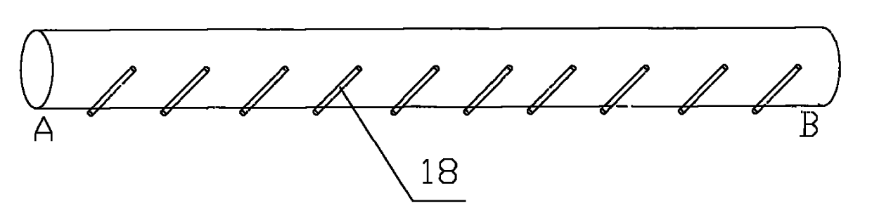
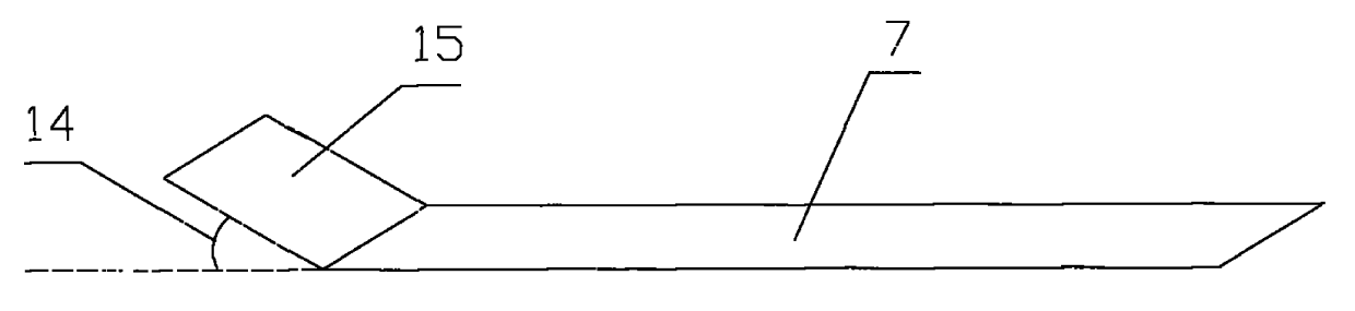
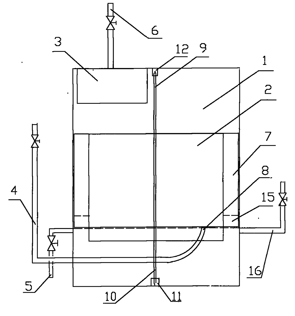
[0020] exist Figure 1~5 In the embodiment, the non-powered gas centrifugal dehumidification and demisting device includes a normal pressure gas dehumidification tank 1, and a completely sealed floating tank 2 floating in the dehumidification tank 1 and capable of horizontal rotation is installed in the dehumidification tank 1 , the upper part of the floating tank 2 is flat, and the lower part can be flat or inverted conical; the upper and lower centers of the floating tank 2 are welded with an upright central shaft, and the upper central shaft 9 gaps are sleeved in the upper cover of the dehumidification tank 1 The upper bearing 12 installed in the center can rotate freely; the lower central shaft 10 is sleeved in the lower bearing 11 installed in the center on the lower bottom surface of the dehumidification tank 1, and can rotate freely; the outer wall of the floating tank 2...


PUM

PropertyMeasurementUnit
angleaaaaaaaaaa

Abstract

The invention discloses an unpowered gas centrifugal dehumidifying and demisting device which comprises a dehumidifying pot and a floating pot, wherein, a plurality of clapboards are evenly distributed on the outer wall of the floating pot and have 60-90 degrees of inclination angle relative to the floating pot; a small clearance is left between each clapboard and the inner surface of the dehumidifying pot; an air inlet pipe is arranged at the outside lower part of the dehumidifying pot, wriggling up obliquely along the inside edge of the dehumidifying pot after going into the humidifying pot and extending to the other side of the dehumidifying pot and in the same level as a drainpipe outlet to form a port; the port is opened upward with 45 degrees relative to the horizontal tangent direction of the inner diameter of the dehumidifying pot, the center of the port is positioned in the middle of the joint part of the clapboards and the water surface; a plurality of short pipes with small inner diameter are arranged in the middle parts beside the immerged part of the air inlet pipe in the dehumidifying pot and are communicated with the air inlet pipe; a dry gas outlet is arranged right above the drainpipe. The floating pot is driven to rotate by the wet gas with only few kilopascals of pressure to make the wet gas be dehydrated among the clapboards. The invention has the advantages of good cooling and dehumidifying effect for wet gas, and unnecessary additional power for centrifugal dehumidification.

Description

technical field [0001] The invention relates to a non-powered gas centrifugal dehumidification and demisting device matched with a water ring vacuum pump, belonging to the technical field of gas-liquid separation. Background technique [0002] Membrane oxygen-enrichment and local oxygen-increasing combustion-supporting energy-saving technology has been researched and applied in my country for more than ten years, and there are dozens of combustion furnaces used, and a number of patents have also been born. However, there are only a few companies such as the National Engineering Research Center of Membrane Technology of the Chinese Academy of Sciences that can really be marketed. The main process is: after the air is filtered by filter cotton and high-efficiency air filter in turn, it is sent to the oxygen-enriched membrane device by the blower, and the clean air flowing through the surface of the oxygen-enriched membrane is extracted by the vacuum pump diaphragm to form an o...

Claims


Application Information

Patent Timeline
Patent Type & Authority Applications(China)
IPC IPC(8): B01D45/16B01D53/26
Inventor 魏伯卿
Owner 魏伯卿
Why Eureka
Try Eureka