
High-precision crown drilling machine used for housing construction ceiling and capable of performing continuous hole drilling

A high-precision, architectural technology, applied in the direction of drilling/drilling equipment, portable drilling rigs, workbenches, etc., can solve the problems of low drilling efficiency, worker fatigue, and inconvenient operation of workers, so as to improve drilling efficiency and reduce labor force , the effect of convenient alignment operation

Inactive Publication Date: 2018-08-28
陆永柱
View PDF7 Cites 14 Cited by
  • Summary
  • Abstract
  • Description
  • Claims
  • Application Information

AI Technical Summary

Problems solved by technology

[0002] In the field of interior decoration, the drilling of suspended ceilings is performed manually by workers climbing up. In the decoration of large shopping malls, the disadvantages of drilling are particularly prominent, and its drilling efficiency seriously delays the efficiency of decoration; The operation is also extremely inconvenient. At the same time, the weight of the entire equipment is borne by the workers, which is easy to cause fatigue of the workers and low drilling efficiency.

Method used


Image

  • High-precision crown drilling machine used for housing construction ceiling and capable of performing continuous hole drilling
  • High-precision crown drilling machine used for housing construction ceiling and capable of performing continuous hole drilling
  • High-precision crown drilling machine used for housing construction ceiling and capable of performing continuous hole drilling

Examples


no. 1 approach )

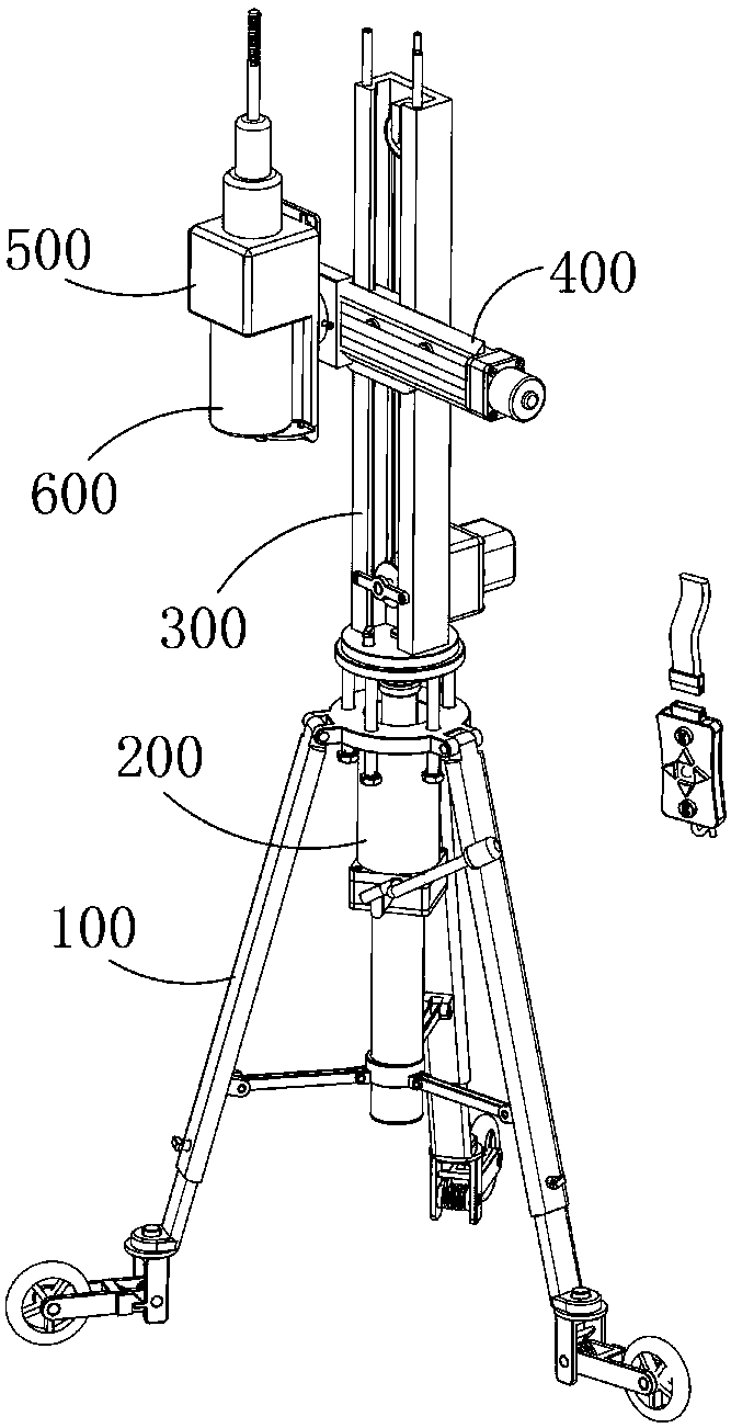
[0071] Such as Figure 5-7 As shown, the above-mentioned power mechanism a330 includes an adjustment motor 331, a fixed pulley a332, a fixed pulley b333, and a connecting rope 334. A fixed bracket 350 and a support rod 340 are installed in the described adjustment slide rail 310, and the support rod 340 is provided with a connection hole, the adjustment slide rail 310 is provided with a through hole, the adjustment motor 331 is fixedly installed on the adjustment slide rail 310 and the power output shaft of the adjustment motor 331 passes through the hole and is located in the connection hole, the fixed pulley a332 The fixed pulley b333 is movably mounted on the fixed bracket 350, and one end of the connecting rope 334 is connected with the fixed pulley a332, bypasses the fixed pulley b333, and the other end is connected with the set pulley b333. It is connected with the slider section of the adjustment slider 320, specifically, the slider section of the adjustment slider 320 ...

no. 2 approach )

[0082] The difference between this embodiment and the first embodiment mainly lies in the structure of the power mechanism a330.

[0083] Such as Figure 12-13 As shown, the above-mentioned power mechanism a330 includes an adjustment motor 331, a gear 335, and a rack 336. The bottom surface of the installation section of the adjustment slider 320 is provided with a slide plate extending toward the ground, and the slide plate is provided with perforations. The adjustment motor 331 is fixedly installed on the slide plate and the power output shaft of the adjustment motor 331 passes through the hole and is located in the adjustment slide rail 310. The gear 335 is fixedly connected to the power output shaft of the adjustment motor 331, and the rack 336 is fixedly installed in the adjustment slide rail 310 and the extension direction of the rack 336 is parallel to the guiding direction of the adjustment slide rail 310, and the rack 336 is engaged with the gear 335; the process of s...


PUM


Abstract

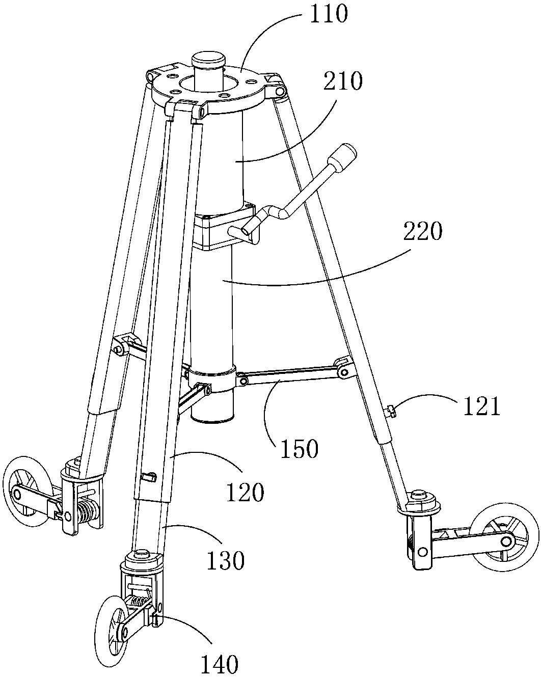
The invention provides a high-precision crown drilling machine used for a housing construction ceiling and capable of performing continuous hole drilling. An electric drill, a supporting mechanism, ajacking mechanism, a height adjusting device and a horizontal displacement device are included; the height adjusting device is used for adjusting the height of the electric drill; the horizontal displacement device is used for adjusting the horizontal displacement of the electric drill; the supporting mechanism is matched with the jacking mechanism to support and fix the electric drill in the workstate; a fixing mechanism is arranged between the electric drill and the horizontal displacement device, and the electric drill is installed on the horizontal displacement device through the fixing mechanism; the horizontal displacement device is connected with the height adjusting device which is connected with the supporting mechanism; the jacking mechanism comprises a jack and a middle column;and a connection component used for connecting the middle column with the supporting mechanism is arranged between the middle column and the supporting mechanism.

Description

technical field [0001] The invention relates to a mechanical device, in particular to a drilling device capable of continuous drilling. Background technique [0002] In the field of interior decoration, the drilling of suspended ceilings is performed manually by workers climbing up. In the decoration of large shopping malls, the disadvantages of drilling are particularly prominent, and its drilling efficiency seriously delays the efficiency of decoration; The operation is also extremely inconvenient, and the weight of the whole equipment is all borne by the workers, which easily causes the fatigue of the workers and the drilling efficiency is low. Contents of the invention [0003] In order to solve the deficiencies of the prior art, the object of the present invention is to provide a drilling equipment capable of continuous drilling. The present invention uses a height and horizontal displacement adjustment device to adjust the height and horizontal displacement of the el...

Claims


Application Information

Patent Timeline
IPC IPC(8): B23B45/14
CPCB25H1/0021B25H1/0035
Inventor 陆永柱
Owner 陆永柱
Learn More