Sausage splitting equipment

A kind of enema and equipment technology, which is applied in sausage making, separated and connected sausages, metal processing, etc. It can solve the problems of hidden dangers in production safety, high labor intensity, cutting fingers, etc., and achieves the effect of easy maintenance and simple equipment structure

Pending Publication Date: 2018-08-28
侯凯希 +1
View PDF0 Cites 13 Cited by
  • Summary
  • Abstract
  • Description
  • Claims
  • Application Information

AI Technical Summary

Problems solved by technology

In the cutting process, it is generally cut by hand with a knife. Manual cutting often causes inconsistencies in the coordination of hands and fingers are cut, which brings hidden dangers to safe production, and manual work cannot guarantee that the length of each cut is consistent, so it needs to be added after cutting. Weighing process, after the weighing is qualified, the follow-up process is produced, the production efficiency is low, and the labor intensity is relatively high

Method used


Image

  • Sausage splitting equipment
  • Sausage splitting equipment
  • Sausage splitting equipment

Examples


Embodiment 1

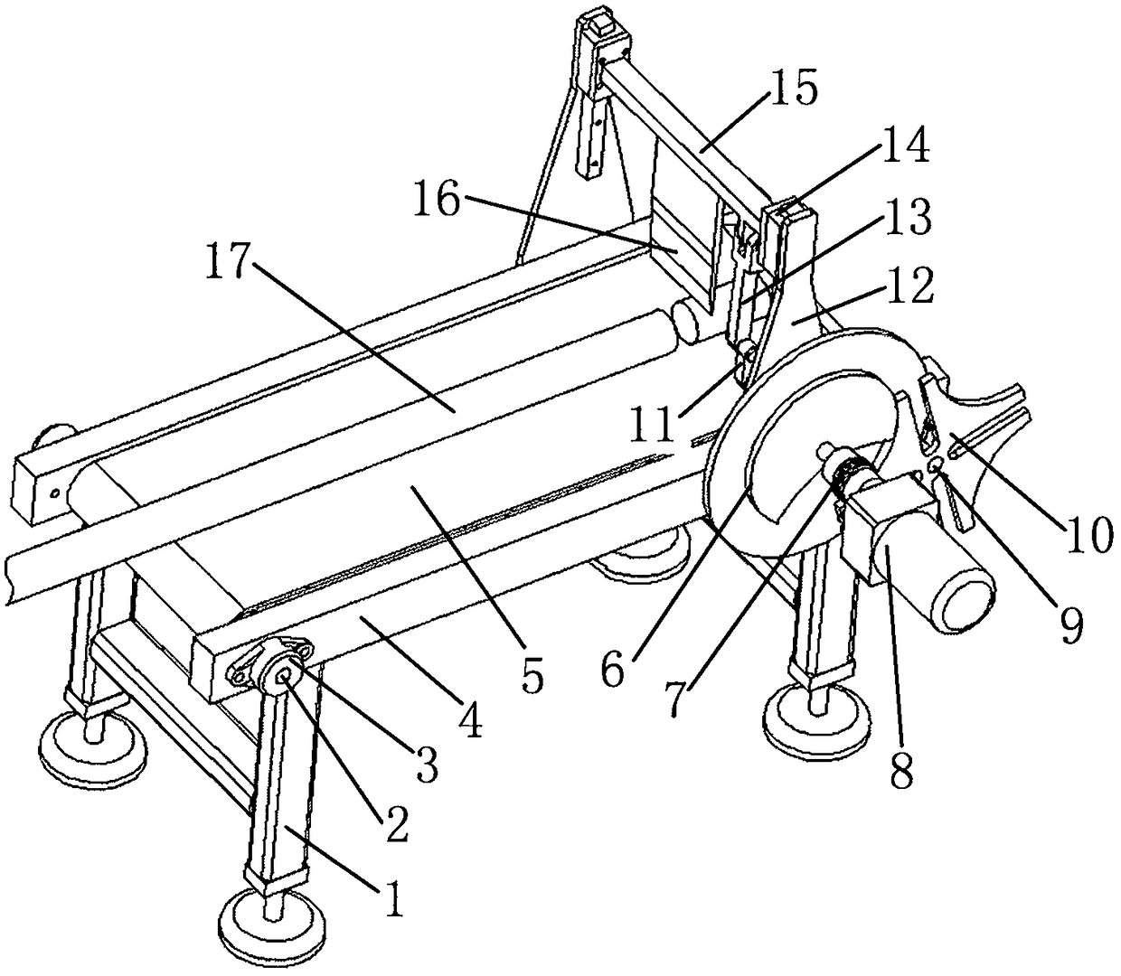
[0016] A sausage cutting device, comprising two side plates 4 arranged in parallel, the two side plates 4 are fixed by legs 1, the front and rear ends of the side plates 4 respectively pass through the driving shaft 9 and the driven shaft 2, the driving shaft 9 A conveyor belt 5 is arranged in the middle of the driven shaft 2, one end of the driving shaft 9 protrudes from the side plate 4 along its axial direction, connects the sheave 10 along the protruding part, and fixes a support plate 12 on the outside of the two side plates 4, wherein The lower part of the support plate 12 on which the sheave 10 is installed is arranged with a driving short shaft 7, one side of the driving short shaft 7 protrudes from the side plate 4, and a notched turntable 6 and a motor 8 are respectively installed, and the other side of the driving short shaft 7 passes through Support plate 12, is fixed with one end of crank 11, and slide rail assembly 14 is all installed in two support plate 12 inner...

Embodiment 2

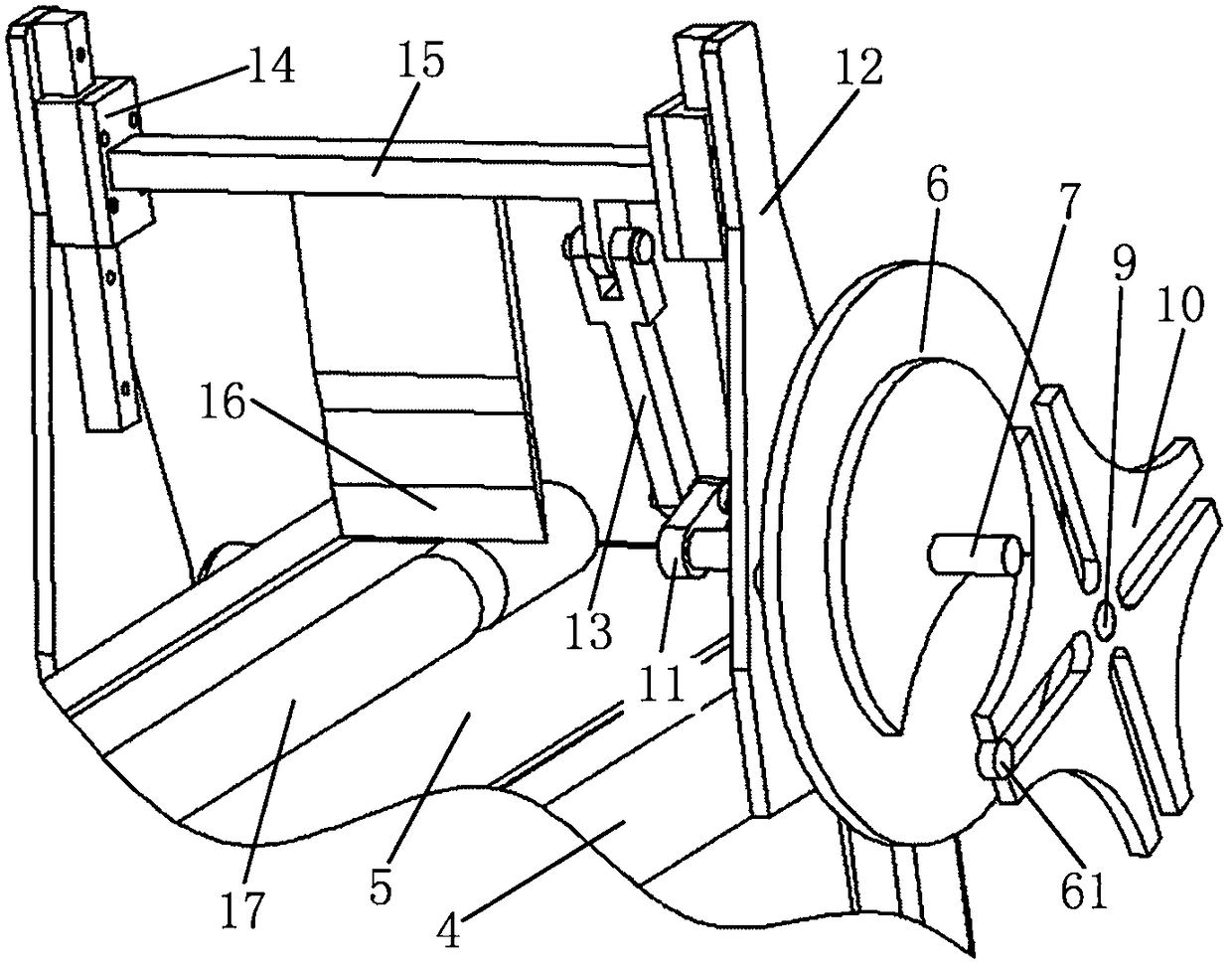
[0022] Such as figure 2 As shown, after the cutter 16 completes the cutting of the enema 17, under the drive of the crank 11, the cutter frame 15 drives the cutter 16 to move upward until it leaves the enema. At this time, the cylindrical block 61 on the notch turntable 6 just enters the groove of the sheave 10, thereby driving the sheave 10 to rotate, thereby making the conveyor belt 5 drive the enema 17 to move forward.

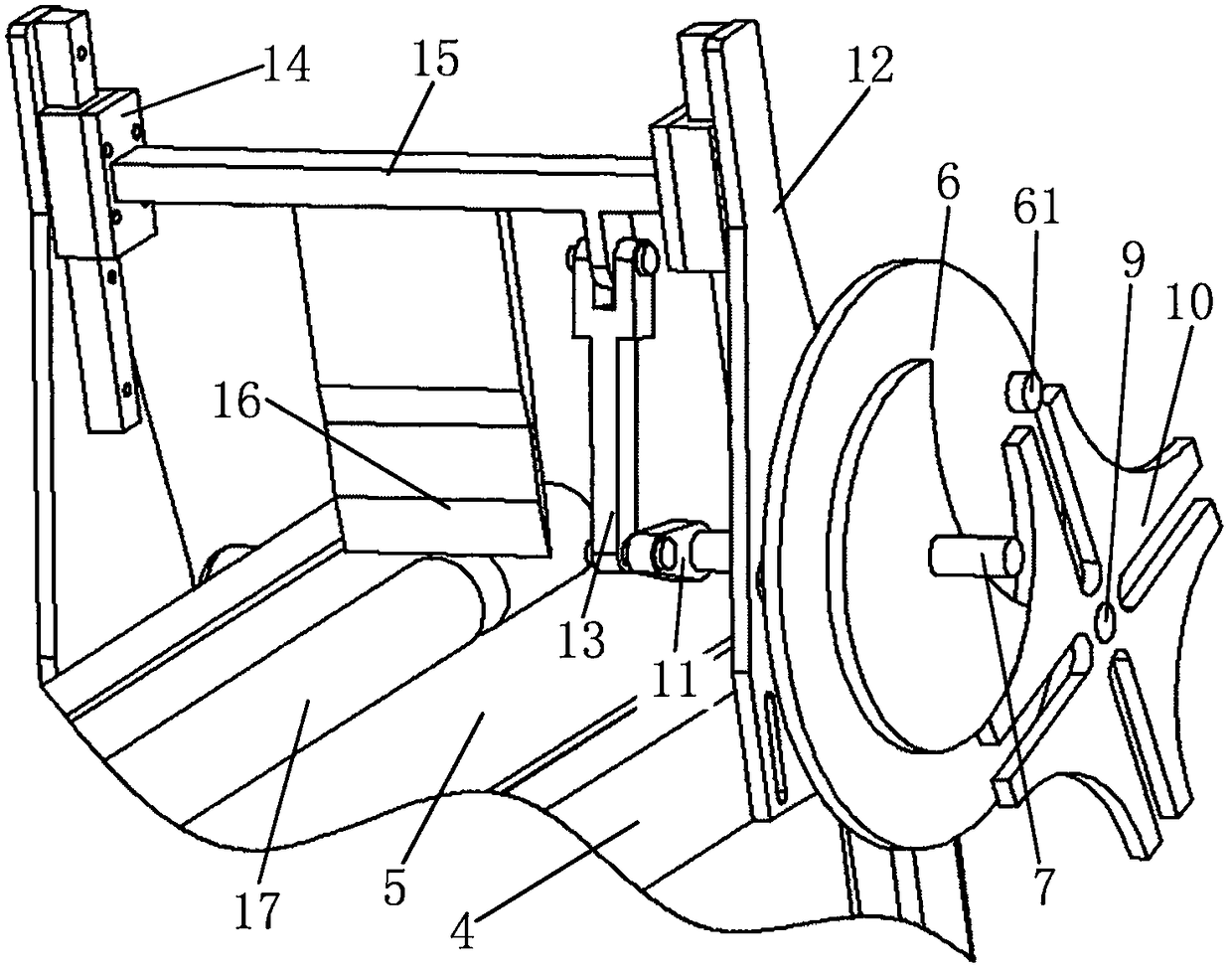
[0023] Such as image 3 As shown, the cylinder block 61 on the notch turntable 6 leaves the groove of the sheave 10, and the conveyor belt 5 no longer drives the enema 17 to move. At this time, under the drive of the crank 11 , the cutter frame 15 drives the cutter 16 to move downward to cut the enema 17 . After the cutting is completed, the cutter 16 moves upwards, and the previous step is repeated.


PUM


Abstract

The invention discloses sausage splitting equipment. Two side plates of the sausage splitting equipment are fixed with supporting legs. A drive shaft penetrates through the front ends of the side plates, and a driven shaft penetrates through the rear ends of the side plates. A conveying belt is arranged between the drive shaft and the driven shaft. One end of the drive shaft protrudes out of the corresponding side plate in the axial direction, and the protruding portion is connected with a sheave. Two supporting plates are fixed to the outer sides of the two side plates correspondingly. A drive short shaft is arranged on the middle lower portion of the supporting plate on the side with the sheave, one side of the drive short shaft protrudes out of the corresponding side plate and is provided with a notched rotary plate and a motor, and the other side of the drive short shaft penetrates through the corresponding supporting plate to be fixedly connected with one end of a crankshaft. Sliding rail assemblies are installed on the inner sides of the two supporting plates. A cutter rest is located above the conveying belt, and the two ends of the cutter rest are connected with the slidingrail assemblies. A lug shaft is arranged below the cutter rest and is close to the side with the sheave. One end of a connecting rod is connected with the lug shaft on the cutter rest, and the otherend of the connecting rod is connected with the crankshaft. A cutter with a cutting edge facing downward is arranged under the cutter rest. The sausage splitting equipment has the characteristics thatsausages are divided consistently, incisions are standard, the structure is simple, and maintenance is easy.

Description

technical field [0001] The invention relates to a food processing device, in particular to a sausage cutting device. Background technique [0002] Fried sausage is an ancient and unique Han traditional snack in our country, and it is also a popular street snack. It has been passed down from the Ming Dynasty to the present. With the increase of population and productivity, traditional manual work can no longer meet the needs of modern people. The industrialized production of enema has become an urgent problem to be solved. [0003] In the industrial production process of sausage, the starch is mixed and extruded into a cylindrical shape, then cut into sections, steamed, and vacuum-packed to form the final product. In the cutting process, it is generally cut by hand with a knife. Manual cutting often causes inconsistencies in the coordination of hands and fingers are cut, which brings hidden dangers to safe production, and manual work cannot guarantee that the length of each ...

Claims


Application Information

Patent Timeline
Patent Type & Authority Applications(China)
IPC IPC(8): B26D1/08B26D5/14B26D7/06A22C11/00
CPCB26D1/08A22C11/006B26D5/14B26D7/0625B26D2210/02
Inventor 侯凯希葛怡琦
Owner 侯凯希
Why Eureka
Try Eureka