Conveying device capable of achieving automatic turnover of box type goods

An automatic flipping and conveying device technology, which is applied in the direction of conveyors, conveyor objects, transportation and packaging, etc., can solve the problems of cargo jamming, cargo wear, manual flipping of cargo, etc., to avoid pollution and wear, solve jamming, The effect of quick flip

Inactive Publication Date: 2018-08-28
SHANDONG LANFU HIGH ENERGY PHYSICS TECH CO LTD
View PDF15 Cites 6 Cited by
  • Summary
  • Abstract
  • Description
  • Claims
  • Application Information

AI Technical Summary

Problems solved by technology

However, there are very few patent documents on cargo delivery devices for industrial high-energy electron accelerators, and few technologies are involved. The service life of the conveying line has not been solved for the smoothness of goods conveying, and the rollers used have no accumulating function
Another example is the utility model patent "A Conveying Device for Electronic Irradiated Products" with the application number of 201620539156.1, which solves the guiding problem in the process of conveying goods, but the guiding is protruding guiding steel strips above the rollers, and guiding grooves at the bottom of the tray. , the friction is sliding friction, the resistance is relatively large, and it is impossible to transport goods without using pallets
None of the above technologies has an automatic flip function. The existing technology has the defects of cargo jamming, cargo wear, and manual flipping of the cargo.

Method used


Image

  • Conveying device capable of achieving automatic turnover of box type goods

Examples


Embodiment Construction

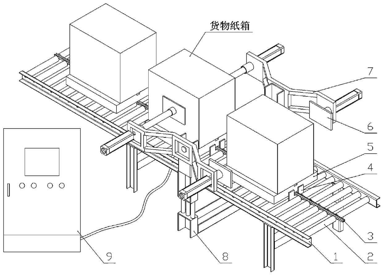
[0021] Installation of conveying device: install the conveying line support (1) to the predetermined place, and level the upper surface; install the accumulative roller (2) and related motor and other parts on the conveying line support (1) with bolts; the guide groove (3) Fixed to the center of the conveying surface of the conveyor line support (1); the tray baffle (4) and its driving cylinder are installed on the conveyor line support (1) with bolts; the flip support (8) is fixed to the ground with expansion bolts, Before installation, it is necessary to adjust its relative position to the conveying line support (1), so that the center of the overturning support (8) coincides with the center of the conveying line support (1); put the overturning arm (7), box chuck (6) and related The components are bolted to the flip bracket (8).

[0022] Operation process: power on the conveying device and adjust to the required conveying speed; place the cargo pallet (5) on the conveying d...


PUM


Abstract

The invention discloses a conveying device capable of achieving automatic turnover of box type goods, and particularly relates to the technology of conveying and automatic turnover of goods irradiatedby industrial electron accelerators. The conveying device is characterized by comprising a conveying line support, accumulation and release type rollers, a guide groove, tray baffles, goods trays, box chucks, turnover arms, a turnover support and a control box. The conveying line support is used for allowing other parts to be installed and bearing the parts, so that a conveying face is formed. Aplurality of accumulation and release type rollers are installed on transverse beams of the conveying line support. The guide groove is fixed to the center of the conveying face of the conveying linesupport. The tray baffles and driving cylinders of the tray baffles are installed on the conveying line support. The box chucks and cylinders at the rear ends of the box chucks are installed on the turnover arms. The turnover support strides over the two sides of a conveying line machine frame to be fixed to the ground, and is used for achieving installation of the turnover arms. The conveying device has the following advantages that the irradiated goods can smoothly move forward, packages can be free of wear, and 180-degree selective automatic turnover of the box type goods can be achieved.

Description

technical field [0001] The invention relates to the technical field of automatic conveying equipment, in particular to the conveying and automatic turning technology of industrial electron accelerator irradiated goods. Background technique [0002] In the complete set of equipment for industrial high-energy (5-10MeV) electron accelerators, the conveying device is used to transport the goods that need radiation sterilization or material modification into the radiation protection channel, so that the goods to be irradiated pass through the electronic scanning box. Be irradiated. According to the radiation depth of electron rays, some packaged goods to be irradiated can penetrate without turning over, and some need to be turned over so that both sides receive irradiation once, so that the goods are irradiated from the surface to the deep part. The speed adjustment range, speed control accuracy, smooth operation, and degree of automation of the conveying device directly affect ...

Claims


Application Information

Patent Timeline
Patent Type & Authority Applications(China)
IPC IPC(8): B65G47/248B65G47/74
CPCB65G47/248B65G47/74B65G2201/0258
Inventor 刘华周周国梁巩新胜马超李传南张庆有
Owner SHANDONG LANFU HIGH ENERGY PHYSICS TECH CO LTD
Why Eureka
Try Eureka