Transmission type squeeze-dewatering device

A technology of extrusion dehydration and extrusion device, which is applied in the direction of liquid/gas/vapor removal with extrusion rollers, processing of textile material carriers, etc., which can solve problems such as trouble, increase work flow, dehydration, etc. Scope and selection, good effect of dehydration

Inactive Publication Date: 2018-08-28
张明霞
View PDF0 Cites 0 Cited by
  • Summary
  • Abstract
  • Description
  • Claims
  • Application Information

AI Technical Summary

Problems solved by technology

[0002] In some textile industries or washing operations, it is necessary to dehydrate the dyed materials. The existing dehydration devices are basically cylindrical structures, which use centrifugal force to rotate at high speed to achieve dehydration. However, in the textile industry, centrifugal dehydration cannot be used, and large After dehydration, most dehydration devices have to go through a transportation process, which increases the work process and is very troublesome

Method used


Image

  • Transmission type squeeze-dewatering device
  • Transmission type squeeze-dewatering device

Examples


Embodiment 1

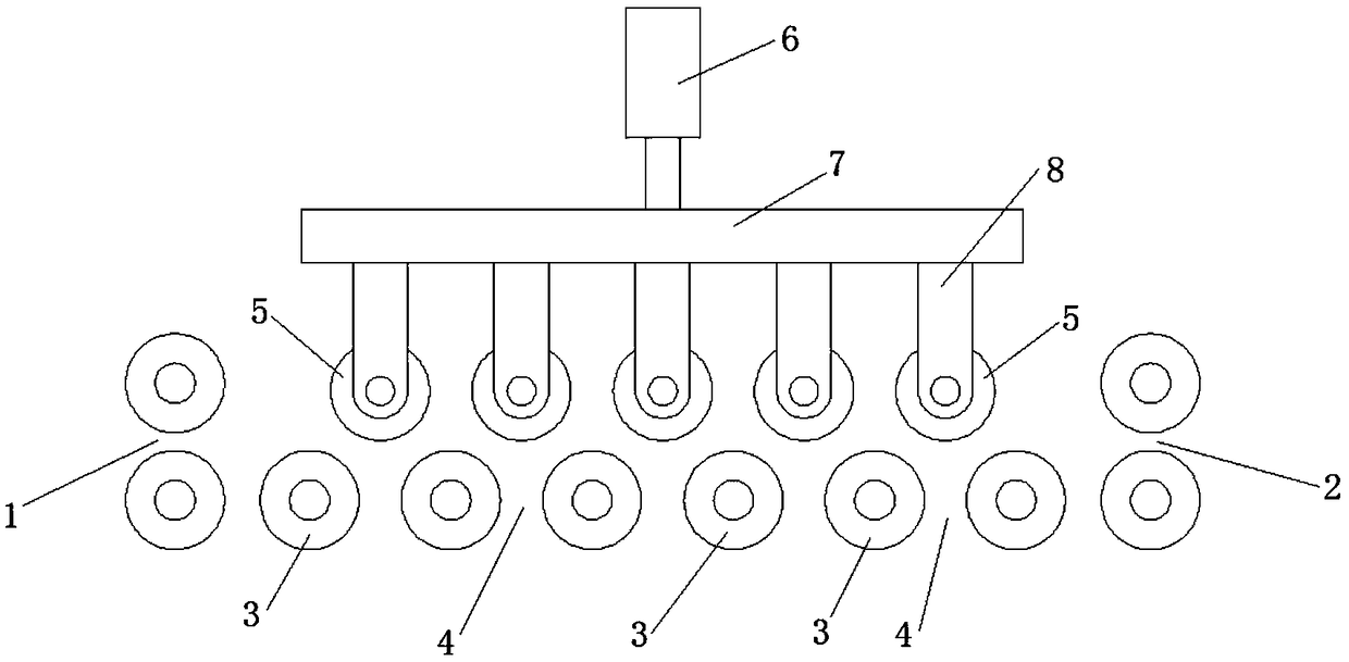
[0015] like figure 1 As shown in the figure, a transmission-type extrusion dehydration device includes a pair of twisted feed wheels 1 arranged at the front end of the left side, a pair of twisted discharge groups 2 arranged in parallel with the pair of twisted feed wheels 1 at the right rear end, and The middle transmission extrusion wheel group; the transmission extrusion wheel group includes a row of parallel transmission wheels 3 and the extrusion device; the transmission wheel 3 and the paired feeding wheel group 1 and the paired twisted discharging wheel group The pair of winches below 2 are arranged in parallel, and a section of squeeze gap 4 is set between adjacent transmission wheels 3, and a squeeze wheel 5 is arranged above the squeeze gap 4; the squeeze wheel 5 is installed On the extrusion device, the extrusion direction of the extrusion device is vertically downward, and the extrusion wheel 5 is driven to press on the corresponding two transmission wheels 3 below...

Embodiment 2

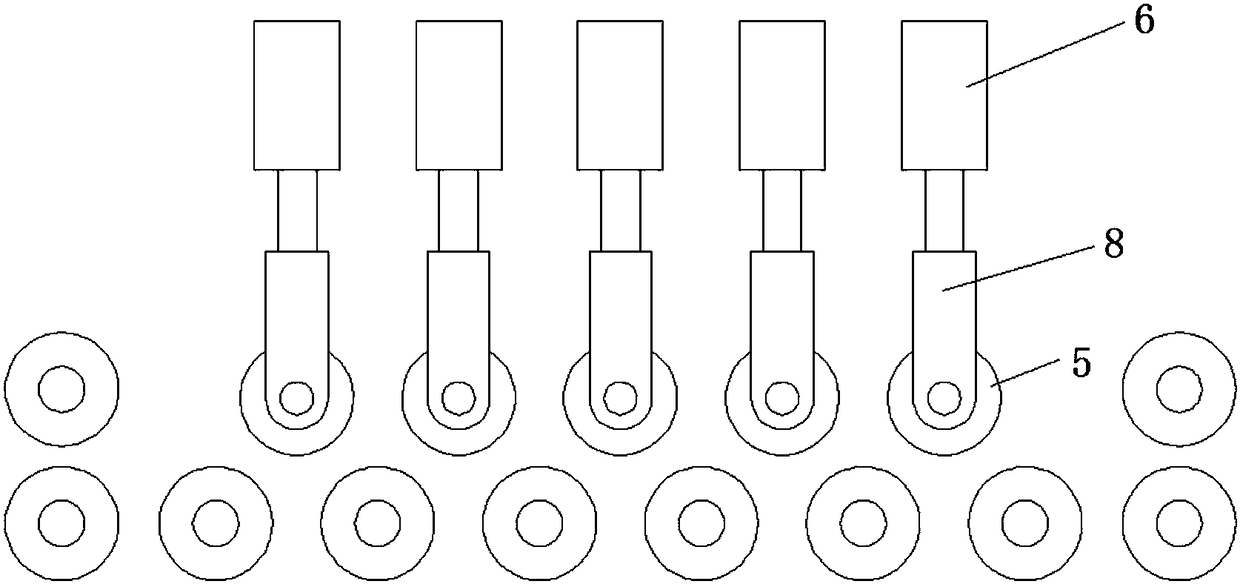
[0018] like figure 2 As shown in the figure, a transmission-type extrusion dehydration device includes a pair of twisted feed wheels 1 arranged at the front end of the left side, a pair of twisted discharge groups 2 arranged in parallel with the pair of twisted feed wheels 1 at the right rear end, and The middle transmission extrusion wheel group; the transmission extrusion wheel group includes a row of parallel transmission wheels 3 and the extrusion device; the transmission wheel 3 and the paired feeding wheel group 1 and the paired twisted discharging wheel group The pair of winches below 2 are arranged in parallel, and a section of squeeze gap 4 is set between adjacent transmission wheels 3, and a squeeze wheel 5 is arranged above the squeeze gap 4; the squeeze wheel 5 is installed On the extrusion device, the extrusion direction of the extrusion device is vertically downward, and the extrusion wheel 5 is driven to press on the corresponding two transmission wheels 3 belo...


PUM


Abstract

The invention discloses a transmission type squeeze-dewatering device which comprises a pair twist feeding wheel group arranged at the front end of the left side, a pair twist discharging wheel grouparranged on the rear end of the right end and parallel to pair twist feeding wheels and a transmission squeezing wheel group arranged in the middle. The transmission squeezing wheel group comprises arow of parallel transmission wheels and a squeezing device. According to the transmission type squeeze-dewatering device, existing transport transmission wheels are converted into transmission wheelswith squeezing gaps, squeezing wheels are arranged above the squeezing gaps of the transmission wheels, dip dyeing cloth is placed onto the transmission wheels from the feeding wheels after dip dyeing, and the upper squeezing wheels are pressed on the two corresponding adjacent transmission wheels under the effect of the squeezing device to squeeze out water for dewatering work; the transmission transport function is not interfered with, squeezing is conducted on the squeezing gaps, the cloth can be squeezed twice through one squeezing wheel, and the dewatering effect is better.

Description

technical field [0001] The invention belongs to a mechanical device, in particular to a transmission-type extrusion dehydration device. Background technique [0002] In some textile industries or washing operations, the impregnated materials need to be dehydrated. The existing dehydration devices are basically cylindrical structures, which use centrifugal force to rotate at high speed to achieve dehydration. However, in the textile industry, centrifugal dehydration cannot be used, and large Most dehydration devices have to go through a one-step transportation process after dehydration, which increases the work flow and is very troublesome. SUMMARY OF THE INVENTION [0003] The object of the present invention is to provide a kind of transmission type extrusion dehydration device for the deficiencies existing in the prior art, and its technical scheme is as follows: [0004] A transmission-type extrusion dehydration device, comprising a pair of twisted feed wheels arranged ...

Claims


Application Information

Patent Timeline
Patent Type & Authority Applications(China)
IPC IPC(8): D06B15/02D06B23/04
CPCD06B15/02D06B23/04
Inventor 张明霞
Owner 张明霞
Why Eureka
Try Eureka