Water surface floating garbage collection robot
A technology of garbage collection and water surface floating, which is applied to the cleaning of open water surfaces, water conservancy projects, construction, etc. It can solve the problems of less garbage on the water surface, threats to health, time-consuming and labor-intensive problems, and achieve the effect of reducing resistance
- Summary
- Abstract
- Description
- Claims
- Application Information
AI Technical Summary
Problems solved by technology
Method used
Image
Examples
Embodiment 2
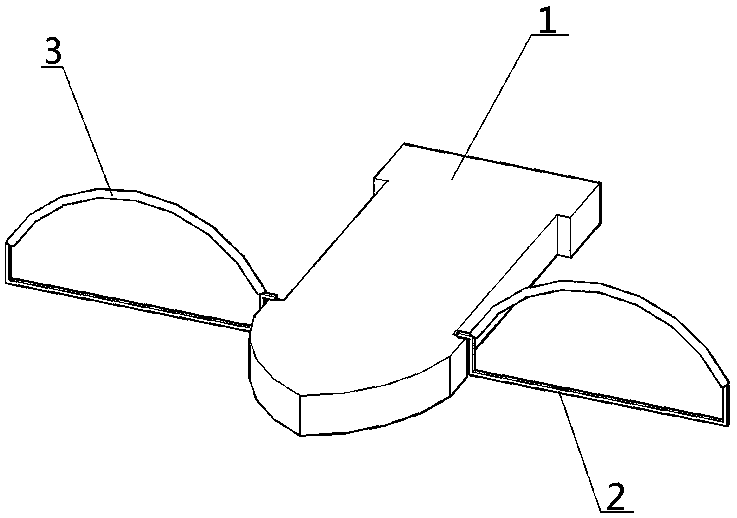
[0040] The overall structure of the collection robot in this embodiment is the same as that in Embodiment 1, the difference is that the propulsion mechanism of this embodiment adopts the structural method in the Chinese invention patent 201510061154.6, the propulsion mechanism includes a power propulsion device and a direction control device, and the power propulsion device is installed Above the hull, the directional control unit is installed behind the power propulsion unit. The power propulsion device includes an engine and a propeller installed on the output shaft of the engine, and the throttle line of the engine is connected to the throttle steering gear. The direction control device comprises an air tail and a rudder gear for controlling the swing direction of the air tail. The remote controller is provided with a button for controlling the throttle servo and a knob for controlling the directional servo. When you need to sail, start the engine through the remote contro...
Embodiment 3
[0042] The overall structure of the collection robot of this embodiment is the same as that of Embodiment 1, the difference is that the structural form of the control assembly in the collection mechanism is different, and the structural form of the control assembly in this embodiment is as follows Figure 10 and 11 As shown: the control assembly specifically includes an electric push rod 16, two transmission rods 15 and two transmission push rods 14, the transmission rod 15 is fixed on the rotating shaft 6, and is arranged opposite to the U-shaped arm 2, and the electric push rod 16 is set On the hull, the push rod head of the electric push rod 16 is connected to the two drive push rods 14 in a hinged form, and the other ends of the two drive push rods 14 are respectively connected to the two drive handle bars 15 in a hinged manner. Rod 14 can control the expansion and retraction of U-shaped arm 2, specifically, when the push rod of electric push rod 14 stretches out, transmis...
PUM
 Abstract
Description
Claims
Application Information
 - R&D
- Intellectual Property
- Life Sciences
- Materials
- Tech Scout
- Unparalleled Data Quality
- Higher Quality Content
- 60% Fewer Hallucinations
Browse by: Latest US Patents, China's latest patents, Technical Efficacy Thesaurus, Application Domain, Technology Topic, Popular Technical Reports.
© 2025 PatSnap. All rights reserved.Legal|Privacy policy|Modern Slavery Act Transparency Statement|Sitemap|About US| Contact US: help@patsnap.com


