Ramming device and ramming method
A technology of tamping plate and rammer, which is applied in the field of tamping device, can solve the problems of difficulty in adjusting the tamping force, limited use occasions, large environmental pollution, etc., and achieves the effects of less moving and control parts, light equipment, and easy operation.
- Summary
- Abstract
- Description
- Claims
- Application Information
AI Technical Summary
Problems solved by technology
Method used
Image
Examples
Embodiment 1
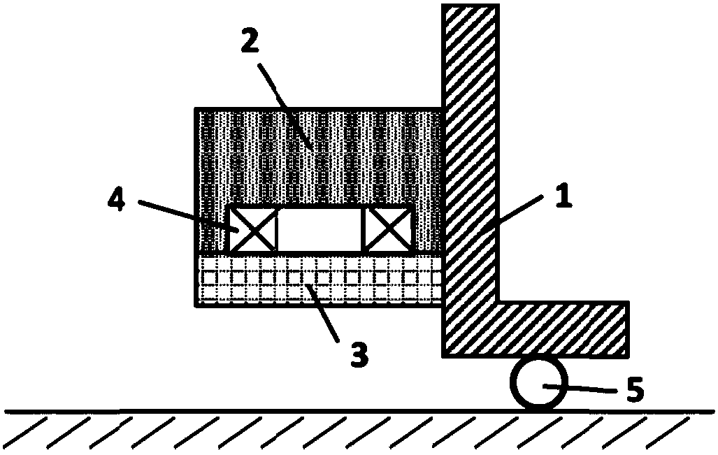
[0049] Such as figure 1 As shown, the overall structure of the tamping device according to the embodiment of the present invention includes: a support base 1 , a tamping hammer 2 , a tamping plate 3 , a coil 4 , and a roller 5 .
[0050] The support base 1 provides support for the rammer 2 and the rammer plate 3, and has a slide rail structure; the rammer 2 is an object with a certain mass, and the rammer 2 is installed on the support base 1 and can move freely on the support base 1; the coil 4 into the groove of the tamper 2 (e.g. Figure 4 shown); the ramming plate 3 can move freely on the slide rail of the support seat 1; the rammer 2 is close to the ramming plate 3, or holds a certain distance in advance. The roller 5 is installed on the support base 3, which can drive the tamping device to move in the direction that needs to be tamped, so as to realize continuous tamping operation.
[0051] The tamping method comprises the following steps:
[0052] (1) In the non-worki...
Embodiment 2
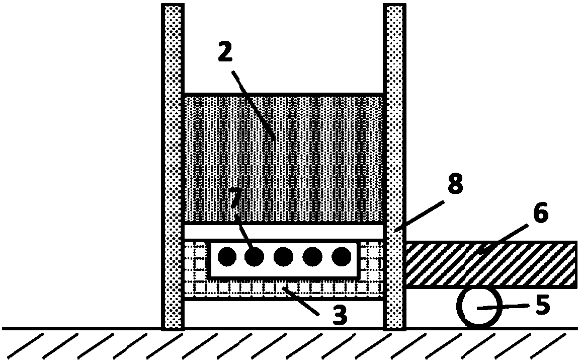
[0060] Such as figure 2 As shown, the overall structure of the tamping device of the embodiment of the present invention includes: a tamping hammer 2 , a tamping plate 3 , a roller 5 , a support plate 6 , an aluminum wire 7 , and a sleeve 8 .
[0061] Tamper 2 and rammer 3 are installed on the sleeve 8; Tamper 3 is provided with a water tank, and aluminum wire 7 is distributed in strips in parallel in the water tank (such as Figure 5 shown), the water tank is filled with water; the sleeve 8 is equipped with a slide rail structure, the sleeve 8 can move up or down as a whole, and can rotate at any angle; Move; the rammer 2 is close to the ramming plate 3, or has a certain initial distance from the ramming plate 3; the ramming plate 3 can be close to the ground, or has a certain initial distance from the ground, so as to ensure a suitable ramming force.
[0062] The tamping method comprises the following steps:
[0063] (1) Tamper 2 and rammer 3 are installed in the inside o...
Embodiment 3
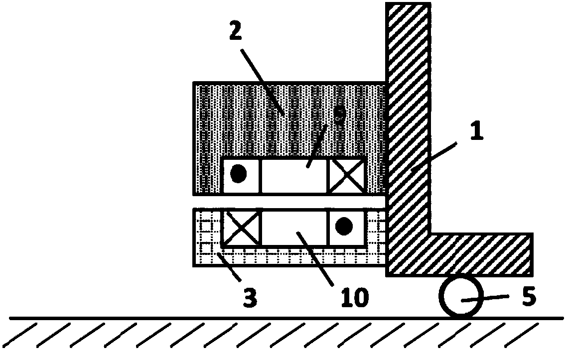
[0072] Such as image 3 As shown, the general structure of the rammer device according to the embodiment of the present invention includes: a support base 1 , a rammer 2 , a tamper plate 3 , a roller 5 , a tamper coil 9 , and a tamper coil 10 .
[0073] The support base 1 provides support for the tamper 2 and the tamper plate 3, and has a slide rail structure; the rammer 2 is provided with a water tank, the tamper coil 9 is embedded in the water tank, and the water tank is filled with water; the top of the tamper plate 3 is provided with a water tank, and the tamper plate The coil 10 is installed inside the water tank, which is filled with water; the tamper 2 and the tamper plate 3 can move up and down in the support seat 1; the tamper 2 is close to the tamper plate 3, or has a certain initial distance from the tamper plate 3; the tamper plate 3 Close to the ground, or have a certain initial distance from the ground to ensure proper tamping force.
[0074] The tamping method ...
PUM
 Abstract
Description
Claims
Application Information
 - R&D
- Intellectual Property
- Life Sciences
- Materials
- Tech Scout
- Unparalleled Data Quality
- Higher Quality Content
- 60% Fewer Hallucinations
Browse by: Latest US Patents, China's latest patents, Technical Efficacy Thesaurus, Application Domain, Technology Topic, Popular Technical Reports.
© 2025 PatSnap. All rights reserved.Legal|Privacy policy|Modern Slavery Act Transparency Statement|Sitemap|About US| Contact US: help@patsnap.com


