Novel pressure-resistant carbon fiber tube

A carbon fiber tube and a new type of technology, applied in the field of carbon fiber tubes, can solve the problems of large structural size of carbon fiber tubes, inability to use carbon fiber tubes, and inability to withstand large ones, and achieve the effects of light overall weight, compact structure, and improved service life.

Pending Publication Date: 2018-08-28
XIHUA UNIV
View PDF0 Cites 1 Cited by
  • Summary
  • Abstract
  • Description
  • Claims
  • Application Information

AI Technical Summary

Problems solved by technology

[0002] Carbon fiber tubes are widely used in kites, aviation model aircraft, lamp brackets, PC equipment shafts, etching machines, medical equipment, new energy vehicles and other fields; their dimensions are stable, electrically conductive, thermally conductive, small in thermal expansion coefficient, self-lubricating, energy-absorbing and shock-resistant, etc. A series of excellent properties, and has the characteristics of light weight, solidity, and high tensile strength; but at present, the carbon fiber tube can only bear a large tensile force, but not a large pressure. If a carbon fiber tube is compressed, it will be along the Cracks are generated in the axial direction, and it is easy to break. This situation is the same as that of bamboo which is stable under tension but easy to split under pressure. Its application range is greatly limited; and in some occasions where the pressure is not high, it is often necessary to increase the diameter and thickness of the carbon fiber tube to prevent splitting, and the structural size of the carbon fiber tube is too large

Method used


Image

  • Novel pressure-resistant carbon fiber tube
  • Novel pressure-resistant carbon fiber tube
  • Novel pressure-resistant carbon fiber tube

Examples


Embodiment Construction

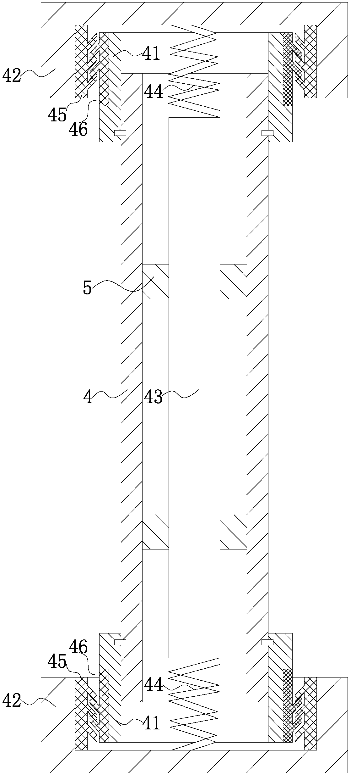
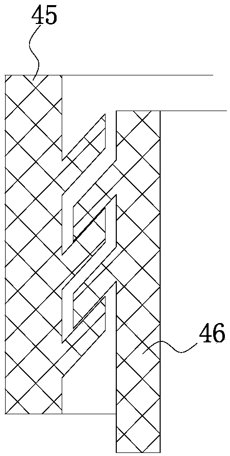
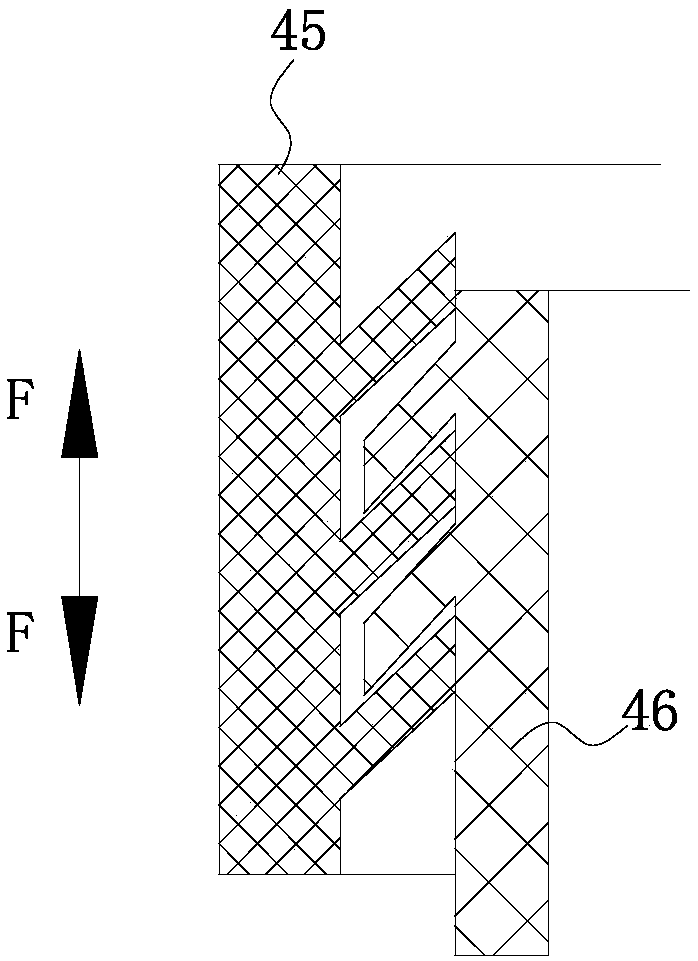
[0014] Such as Figure 1-Figure 2 A new type of compression-resistant carbon fiber tube is shown, the two ends of the carbon fiber tube 4 are bonded to one end of the metal pipe joint 41 or a circlip is arranged between the two to limit the axial displacement of the two, and the metal The other end of the pipe joint 41 snaps into the positioning hole provided along the axial direction of the positioning sleeve 42, and the positioning hole of the metal pipe joint 41 and the positioning sleeve 42 adopts an interference fit or uses a circlip to limit the axial displacement of the two; the positioning hole The inner side wall of the first rubber ring 45 is fixedly connected to the outer side wall of the first rubber ring 45, and the inner side wall of the first rubber ring 45 at the upper end of the carbon fiber tube 4 is provided with an upwardly inclined serrated protrusion, and the joint 41 is inserted into a part of the outer side of the positioning hole. Fixedly connected wit...


PUM


Abstract

The invention particularly relates to a novel pressure-resistant carbon fiber tube with the compact structure. Each of the two ends of the carbon fiber tube is bonded to one end of a metal pipe joint,and the other end of the metal pipe joint is clamped into a locating hole. The inner sidewall of each locating hole is fixedly connected with the outer sidewall of a first rubber ring. The inner sidewall of the first rubber ring located at the upper end of the carbon fiber tube is provided with an upward inclined serrated convex part. The outer side face of the portion, located in the corresponding locating hole in a sleeved mode, of each joint is fixedly connected with the inner side face of a second rubber ring. The outer sidewall of a second rubber ring located at the upper end of the carbon fiber tube is provided with a downward inclined serrated convex part. Each upward inclined serrated convex part and the downward inclined serrated convex part are arranged in a staggered mode. Tensile force is transmitted through the carbon fiber tube. Pressure is transmitted through a metal pressure rod. The carbon fiber tube is prevented from being pressed. The service life of the carbon fiber tube is effectively prolonged.

Description

technical field [0001] The invention relates to the technical field of carbon fiber tubes, in particular to a novel compression-resistant carbon fiber tube. Background technique [0002] Carbon fiber tubes are widely used in kites, aviation model aircraft, lamp brackets, PC equipment shafts, etching machines, medical equipment, new energy vehicles and other fields; their dimensions are stable, electrically conductive, thermally conductive, small in thermal expansion coefficient, self-lubricating, energy-absorbing and shock-resistant, etc. A series of excellent properties, and has the characteristics of light weight, solidity, and high tensile strength; but at present, the carbon fiber tube can only bear a large tensile force, but not a large pressure. If a carbon fiber tube is compressed, it will be along the Cracks are generated in the axial direction, and it is easy to break. This situation is the same as that of bamboo which is stable under tension but easy to split under...

Claims


Application Information

Patent Timeline
IPC IPC(8): F16L27/12F16L9/14F16L57/02F16L57/06
CPCF16L9/14F16L27/12F16L57/02F16L57/06
Inventor 陈子龙
Owner XIHUA UNIV
Why Eureka
Try Eureka