
LED (Light Emitting Diode) device and LED lamp

A technology of LED devices and light-transmitting boards, which is applied in semiconductor devices, electrical components, circuits, etc., can solve problems such as LED device failure, and achieve the effects of avoiding failure, enhancing connection strength, and avoiding quality defects

Inactive Publication Date: 2018-08-28
SHENZHEN LINGDU INTELLIGENT CONTROL TECH CO LTD
View PDF0 Cites 1 Cited by
  • Summary
  • Abstract
  • Description
  • Claims
  • Application Information

AI Technical Summary

Problems solved by technology

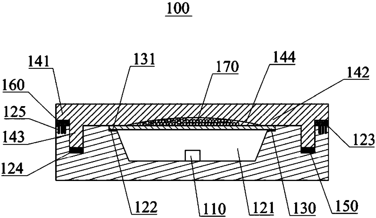
[0004] The main purpose of the present invention is to provide an LED device and LED lamp, aiming to solve the failure and glare problems of LED devices caused by aging and corrosion

Method used


Image

  • LED (Light Emitting Diode) device and LED lamp
  • LED (Light Emitting Diode) device and LED lamp

Examples


Embodiment Construction

[0025] The following will clearly and completely describe the technical solutions in the embodiments of the present invention with reference to the accompanying drawings in the embodiments of the present invention. Obviously, the described embodiments are only part of the embodiments of the present invention, not all of them. Based on the embodiments of the present invention, all other embodiments obtained by persons of ordinary skill in the art without creative efforts fall within the protection scope of the present invention.

[0026] It should be noted that all directional indications (such as up, down, left, right, front, back...) in the embodiments of the present invention are only used to explain the relationship between the components in a certain posture (as shown in the accompanying drawings). Relative positional relationship, movement conditions, etc., if the specific posture changes, the directional indication will also change accordingly.

[0027] In addition, in t...


PUM


Abstract

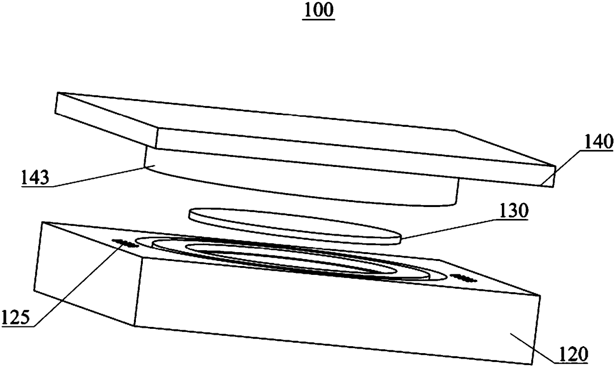
The invention discloses an LED (Light Emitting Diode) device and an LED lamp. The LED device comprises a substrate, a first light transmission plate and a second light transmission plate. A cavity isformed in the substrate, an LED chip is arranged in the cavity, a stepped face is formed at an open end of the cavity, and a seal groove is formed in the peripheral face of the cavity. The first lighttransmission plate is arranged on the stepped face. The second light transmission plate comprises a peripheral part and an intermediate part, an annular lug matched with the seal groove is arranged between the peripheral part and the intermediate part, a desiccant is used for filling between the peripheral part and the intermediate part, the thickness of the peripheral part is smaller than that of the intermediate part, the intermediate part is opposite to the cavity and presses the first light transmission plate, a microporous layer opposite to the peripheral part is arranged on the peripheral face, a bonding adhesive is used for filling between the peripheral part and the substrate and infiltrates into the microporous layer, a concave spherical face with an opening facing to the first light transmission plate is formed in the intermediate part, and a plurality of glass micro-beads are arranged in the intermediate part. According to the LED device and the LED lamp, outside corrosivesubstances are subjected to dual isolation, the failure rate of the LED device can be effectively improved, and the LED device has an anti-dazzle effect.

Description

technical field [0001] The invention relates to the technical field of LED lighting, in particular to an LED device and an LED lamp. Background technique [0002] LED (Light Emitting Diode), commonly known as light-emitting diode, as a semiconductor component, based on its semiconductor characteristics, LED is very sensitive to the current passing through it, and a very small current can make it glow, so LED lamps are used as energy-saving lamps. widely used. At present, in the production process of LED devices, light-transmitting organic materials such as silica gel and epoxy resin are usually used to seal and protect the LED light-emitting part (mainly referring to the LED chip). It is easy to age or undergo chemical reactions in harsh environments, and the contact surface between sealing materials such as silica gel and epoxy resin and the LED chip mounting substrate (metal) is formed to allow external corrosive substances (such as water vapor, corrosive gases, etc.) to ...

Claims


Application Information

Patent Timeline
Patent Type & Authority Applications(China)
IPC IPC(8): H01L33/58H01L33/52H01L33/48
CPCH01L33/58H01L33/48H01L33/52
Inventor 徐瑞
Owner SHENZHEN LINGDU INTELLIGENT CONTROL TECH CO LTD
Learn More