
Nano vaporization fogging device

A fog-making device and nano-technology, which is applied in the field of mechanical equipment and electrical equipment, can solve the problems of high liquid mist temperature, low fog-making efficiency, and high manufacturing cost, and achieve high fog-making efficiency, moderately adjustable liquid mist temperature, and manufacturing low cost effect

Pending Publication Date: 2018-08-31
HANGZHOU QINGKE ENERGY SAVING ENVIRONMENTAL PROTECTION TECH CO LTD
View PDF2 Cites 6 Cited by
  • Summary
  • Abstract
  • Description
  • Claims
  • Application Information

AI Technical Summary

Problems solved by technology

In the market, high-temperature heating or ultrasonic vibration is generally used to produce spray, but this technical solution has many disadvantages such as low fog-making efficiency, high liquid mist temperature, complicated process, and high manufacturing cost.

Method used


Image

  • Nano vaporization fogging device
  • Nano vaporization fogging device
  • Nano vaporization fogging device

Examples


Embodiment 1

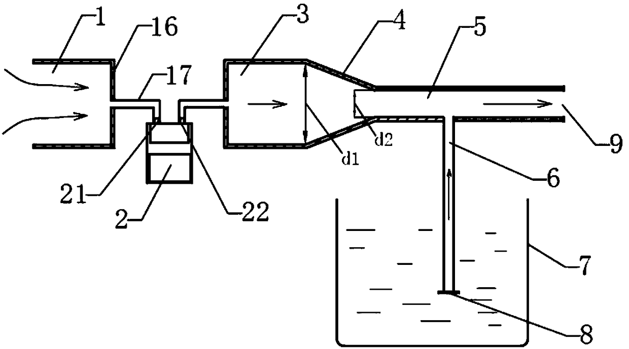
[0029] Such as figure 1 As shown, the nano-vaporization fog-making device includes: gas inlet pipe 1, gas pump 2, gas outlet pipe 3, reducer pipe 4, throat pipe 5, vaporization pipe 6, liquid tank 7, injection port 9, the liquid tank The opening of 7 is an open state, and the liquid tank 7 communicates with atmospheric pressure.

[0030] The gas pump 2 is used to pressurize the gas. The suction port 21 and the delivery port 22 of the gas pump 2 are sequentially connected to the gas inlet pipe 1 and the gas outlet pipe 3 .

[0031] The gas inlet pipe 1 and the gas outlet pipe 3 are provided with a cover 16 at the connecting end of the gas pump 2, and the center of the cover 16 is connected with a gas thin tube 17, and the two ends of the gas thin tube 17 are connected with the corresponding gas pump respectively. The suction port 21 and the delivery port 22 of 2 are connected.

[0032] The reducer 4 and the throat 5 form a jet tube, and the inner diameter of the reducer 4 is ...

Embodiment 2

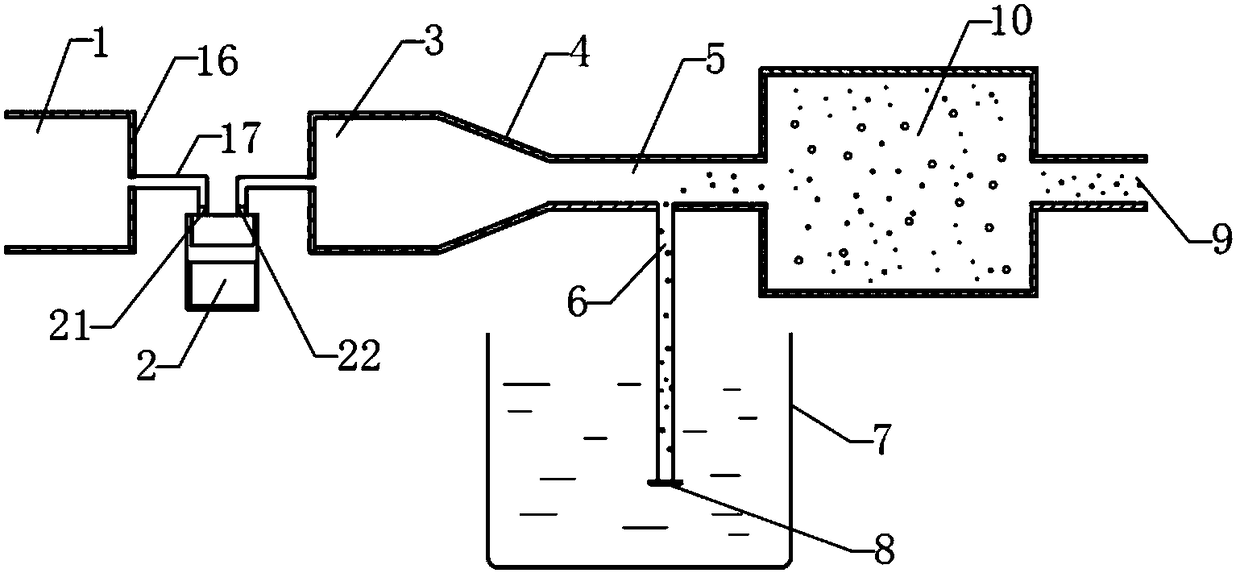
[0048] Such as figure 2 As shown, a buffer chamber 10 is provided at the injection port 9, so that the gas, steam and liquid particles can be mixed more fully.

[0049] Other structures are the same as in Embodiment 1.

Embodiment 3

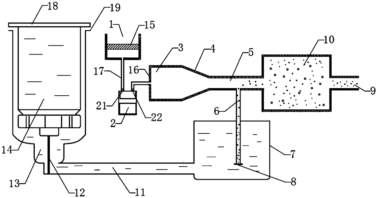
[0051] Such as image 3 As shown, the top of the liquid tank 7 is closed, and the liquid tank 7 is provided with an automatic liquid replenishment device. The automatic liquid replenishment device includes a liquid replenishment tank 14, a liquid replenishment tank 13 and a liquid replenishment rod 12. The liquid replenishment tank 13 is connected to the liquid tank through a connecting pipe 11. 7 is connected, and the liquid replenishment tank 13 is vertically provided with a liquid replenishment rod 12. When the liquid replenishment tank 14 filled with liquid is placed in the liquid replenishment tank 13, the automatic locking device in the cover of the liquid replenishment tank 14 is pushed open by the liquid replenishment rod 12, and the liquid replenishment tank The liquid in 14 flows into the liquid replenishing tank 13, and automatically replenishes liquid in the liquid tank 7 through the connecting pipe 11.

[0052] The top of the liquid replenishment tank 14 is provid...


PUM


Abstract

The invention discloses a nano vaporization fogging device. A gas inlet tube (1) is connected with the sucking hole (21) of a gas pump (2); the discharge hole (22) of the gas pump (2) is connected with a gas outlet tube (3); the gas outlet tube (3) is connected with the large diameter end of a reducing pipe (4); the small diameter end of the reducing pipe (4) is connected with a venturi tube (5);the venturi tube (5) is arranged horizontally or in an inclined manner; a vaporization tube (6) is connected below the venturi tube (5); the lower end of the vaporization tube (6) is inserted below the liquid level inside a liquid tank (7); an ejection hole (9) is formed in the tail end of the venturi tube (5). By adopting the nano vaporization fogging device, an intense low-pressure environment is constructed by virtue of jet flow principles, so that a liquid can be vaporized to generate nano vapor and is mixed with high-speed air after air flow induction , then nano atomization can be achieved, and the device has multiple advantage of being high in vaporization efficiency, moderate and adjustable in liquid mist temperature, simple in process, low in manufacturing cost, and the like.

Description

technical field [0001] The invention relates to a nano-vaporization fog-making device, which belongs to the field of mechanical equipment, in particular to the field of electrical equipment such as cleaning, humidification, medical treatment, beauty treatment, and nursing for manufacturing nano-spray. Background technique [0002] Nano gas-liquid mixed spray is a mixture of high-pressure gas, steam and very fine liquid particles, which has a powerful cleaning function. In the market, high-temperature heating or ultrasonic vibration is generally used to produce spray, but this technical solution has many shortcomings such as low fog-making efficiency, high liquid mist temperature, complicated process, and high manufacturing cost. Contents of the invention [0003] In order to solve the above existing problems, the present invention discloses a nano-vaporization fog-making device, which utilizes the principle of jet flow to produce nano-mixed spray of high-pressure gas, stea...

Claims


Application Information

Patent Timeline
Patent Type & Authority Applications(China)
IPC IPC(8): B01F5/04B01F3/02B01F3/04B01F23/10
CPCB01F23/12B01F23/19B01F23/213B01F23/216B01F25/31243B01F25/315
Inventor 唐峰姜峰袁超
Owner HANGZHOU QINGKE ENERGY SAVING ENVIRONMENTAL PROTECTION TECH CO LTD
Learn More