Tubular reactor

A tubular reactor and reaction technology, which is applied in the field of medical machinery and chemical industry, can solve the problems of poor heat exchange effect, large floor area, and too long pipes, etc., to overcome poor heat exchange effect and reduce floor space The effect of improving the area and heat transfer effect

Pending Publication Date: 2018-08-31
SHANDONG HIMILE CHEM TECH +1
View PDF0 Cites 11 Cited by
  • Summary
  • Abstract
  • Description
  • Claims
  • Application Information

AI Technical Summary

Problems solved by technology

[0008] Therefore, the technical problem to be solved by the present invention is to overcome the defects that the tubular reactor in the prior art has a large footprint, too long pipelines are not easy to realize in industry, and the heat exchange effect is not good, so as to provide a tubular reactor

Method used


Image

  • Tubular reactor
  • Tubular reactor
  • Tubular reactor

Examples


no. 1 approach 、 no. 2 approach and no. 3 approach

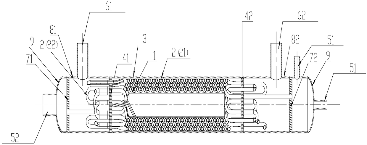
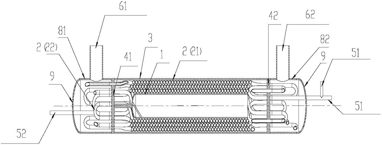
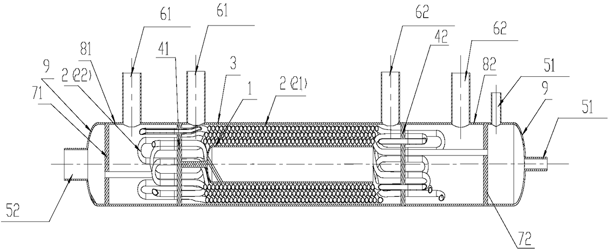
[0082] In the first and second embodiments of the present invention, there are two reactive fluid inlet connectors 51, one reactive fluid outlet connector 52, one heat exchange fluid inlet connector 61, and one heat exchange fluid outlet connector 62, see figure 1 and 2 As shown; and the third embodiment of the present invention has two reaction fluid inlet joints 51, one reaction fluid outlet joint 52, and two heat exchange fluid inlet joints 61 (one of which is arranged on the first tube plate 71 and the first perforated plate 41, and the other is arranged between the first perforated plate 41 and the mandrel 1), and there are two heat exchange fluid outlet joints 62 (one of which is arranged on the second tube plate 72 and the second between the perforated plates 42, and the other is disposed between the second perforated plate 42 and the mandrel 1), as shown in FIG. 3 .

[0083]The reaction fluid can be passed through the reaction fluid inlet connection, especially more t...


PUM


Abstract

The invention provides a tubular reactor. The reactor comprises a reaction tube (2) capable of containing reaction fluid which passes through and reacts in the tube, the reaction tube (2) comprises aplurality of spiral tubes (21), the spiral tubes (21) spirally wind, or the spiral tubes (21) are arranged in a spiral array, and the spiral tubes (21) are sequentially connected in series to form reaction tubes. According to the reactor, the residence time of the reaction fluid is greatly increased, the problems in the prior art that a pipeline needs to be processed too long and cannot be easilyachieved in the industry when the reaction rate is low are solved, the floor space is effectively reduced, the reactor is well achieved, the heat exchange effect is improved, the flow length of the fluid is increased, the reaction residence time is ensured, and the reactor is suitable for reactions with large residence time.

Description

technical field [0001] The invention belongs to the technical fields of chemical engineering and medical machinery, and in particular relates to a tubular reactor. Background technique [0002] Tubular reactor is a continuously operating reactor with a tubular shape and a large length-to-diameter ratio. Such reactors can be very long, for example, reactor tubes for propylene dimerization can be measured in kilometers. The structure of the reactor can be a single tube or a multi-tube parallel connection; it can be an empty tube, such as a tube cracking furnace, or a filled tube filled with granular catalysts in the tube for heterogeneous catalytic reactions. [0003] Traditional tubular reactors have the following disadvantages: [0004] 1) It occupies a large area and is fixed by brackets; [0005] 2) When the reaction rate is very low, the required pipeline is too long, which is difficult to realize industrially; [0006] 3) Heating and cooling need to set up casing or ...

Claims


Application Information

Patent Timeline
Patent Type & Authority Applications(China)
IPC IPC(8): B01J19/24B01J19/02
CPCB01J19/02B01J19/243B01J2219/0277B01J2219/0286B01J2219/029
Inventor 厉晓英丁全有杨茜魏晓张恭运唐立星魏猛赵平
Owner SHANDONG HIMILE CHEM TECH
Why Eureka
Try Eureka