Check patentability & draft patents in minutes with Patsnap Eureka AI!

An oil barrel pouring device

An oil pouring and equipment technology, applied in packaging, loading/unloading, liquid handling, etc., can solve the problems of unstable process and inconvenient adjustment of the oil pouring device, and achieve the effects of reasonable structure design, good stability and simple operation.

Inactive Publication Date: 2020-07-28
台州吉联塑模股份有限公司
View PDF4 Cites 0 Cited by
  • Summary
  • Abstract
  • Description
  • Claims
  • Application Information

AI Technical Summary

Problems solved by technology

[0003] The purpose of the present invention is to solve the disadvantages of unstable process and inconvenient adjustment of the existing oil pouring device, and propose a kind of oil pouring equipment for oil barrels, which not only has good stability, but also can be adjusted according to actual needs. Helps to pour oil smoothly

Method used


Image

  • An oil barrel pouring device
  • An oil barrel pouring device
  • An oil barrel pouring device

Examples


Embodiment Construction

[0019] The following will clearly and completely describe the technical solutions in the embodiments of the present invention with reference to the accompanying drawings in the embodiments of the present invention. Obviously, the described embodiments are only some, not all, embodiments of the present invention.

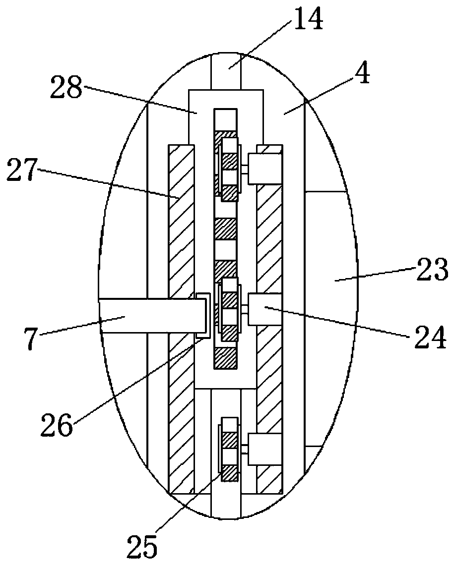
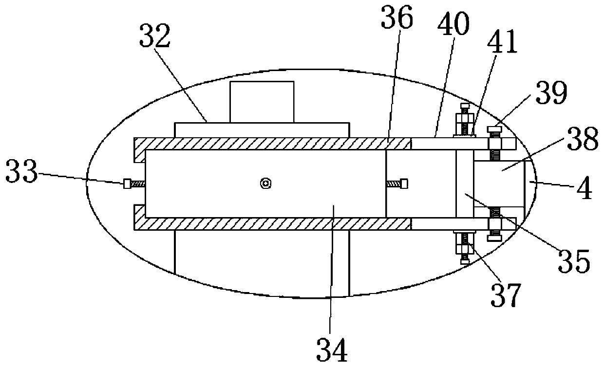
[0020] refer to Figure 1-4, an oil barrel pouring device, comprising a base 1, the upper end of the base 1 is vertically provided with a first threaded rod 19, the upper end of the first threaded rod 19 is fixedly connected with a horizontal plate 15, and the outer wall of the first threaded rod 19 is threaded The driven wheel 21 is connected, and the outer sidewall of the first threaded rod 19 is slidably connected with a sliding plate, and the sliding plate is positioned on the upper side of the driven wheel 21, and the driven wheel 21 and the sliding plate are connected by a rotating block 22, and the side wall of the sliding plate A fixed block 10 is fixedly con...


PUM


Abstract

The invention discloses an oil drum pouring apparatus. The oil drum pouring apparatus comprises a base. A first threaded rod is vertically arranged at the upper end of the base. A horizontal plate isfixedly connected with the upper end of the first threaded rod. A driven wheel is in thread connection with the outer side wall of the first threaded rod. A sliding plate is in sliding connection withthe outer side wall of the first threaded rod and is located on the upper side of the driven wheel. The driven wheel and the sliding plate are connected through a rotary block. A fixed block is fixedly connected with the side wall of the sliding plate. A first servo motor is fixedly connected with the bottom side wall of the fixed block. A first driving wheel is fixedly connected with the tail end of an output shaft of the first servo motor. The first driving wheel and the driven wheel are meshed with each other. A round plate is rotationally connected with the side wall of the end, away fromthe sliding plate, of the fixed block. The oil drum pouring apparatus is reasonable in structural design and easy to operate, has very good stability and can be adjusted as needed as well, and then smooth operation of pouring oil is facilitated.

Description

technical field [0001] The invention relates to the technical field of petroleum, in particular to an oil barrel pouring device. Background technique [0002] Petroleum, one of the main objects of geological exploration, is a viscous, dark brown liquid known as the "blood of industry." There are oil reserves in parts of the upper crust. The main component is a mixture of various alkanes, cycloalkanes, and aromatic hydrocarbons. Petroleum is mainly used as fuel oil and gasoline, and is also a raw material for many chemical industry products, such as solutions, fertilizers, pesticides, and plastics. Most of them will be placed in oil barrels, and if needed, they will be pumped out, but in some smaller oil barrels, it will be a little troublesome to use the oil pump to pump them out, which requires an oil pouring device to solve the problem. The traditional oil pouring The device simply tilts the oil barrel, which will cause the oil barrel to be extremely unstable and may cau...

Claims


Application Information

Patent Timeline
Patent Type & Authority Patents(China)
IPC IPC(8): B65G65/23
CPCB65G65/23
Inventor 陈广进
Owner 台州吉联塑模股份有限公司
Features
  • R&D
  • Intellectual Property
  • Life Sciences
  • Materials
  • Tech Scout
  • Unparalleled Data Quality
  • Higher Quality Content
  • 60% Fewer Hallucinations
Learn More