Multi-layer sleeve tube cutter

A multi-layer casing and tool seat technology, which is applied in wellbore/well parts, earthwork drilling and production, etc., can solve the problems of difficult secondary positioning and low service life, so as to improve cutting efficiency, long service life and reduce operating costs Effect

Pending Publication Date: 2018-08-31
SHANDONG SHENGLI PETROLEUM EQUIP IND TECH RES INST
View PDF0 Cites 6 Cited by
  • Summary
  • Abstract
  • Description
  • Claims
  • Application Information

AI Technical Summary

Problems solved by technology

[0003] The purpose of the present invention is to provide a multi-layer casing cutter, which solves the problems and deficiencies in the existing cutter technology, and can complete the cutting of multi-layer casing in one trip without changing the cutter, greatly improving the construction efficiency and solving the problem. Solved the problem of secondary positioning difficulties caused by the replacement of existing cutters
The tool is designed with an automatic cutter recovery system. After the cutting is completed, the cutter is automatically retracted into the body, which solves the risk of the existing cutter not being automatically retracted into the main body of the knife holder after the cutting is completed.
The cutter tooth surface of the tool is sharp, with high hardness and long service life. In addition, there are multiple through holes on it, which can clean the cutter to a certain extent, and effectively overcome the problems of severe wear and low service life of the existing cutter.

Method used


Image

  • Multi-layer sleeve tube cutter
  • Multi-layer sleeve tube cutter
  • Multi-layer sleeve tube cutter

Examples


Embodiment Construction

[0020] In order to make the purpose, technical solutions and advantages of the embodiments of the present invention clearer, the technical solutions in the embodiments of the present invention will be clearly and completely described below in conjunction with the drawings in the embodiments of the present invention. Obviously, the described embodiments It is a part of embodiments of the present invention, but not all embodiments. The components of the embodiments of the invention generally described and illustrated in the figures herein may be arranged and designed in a variety of different configurations. Accordingly, the following detailed description of the embodiments of the invention provided in the accompanying drawings is not intended to limit the scope of the claimed invention, but merely represents selected embodiments of the invention. Based on the embodiments of the present invention, all other embodiments obtained by persons of ordinary skill in the art without cre...


PUM


Abstract

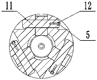
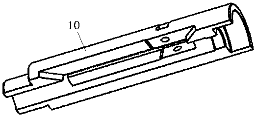
The invention relates to a multi-layer sleeve tube cutter. The cutter comprises an upper joint, a piston, a central pipe, a piston sleeve, a cutter seat body, a cutter, a lower central pipe and a lower joint, the upper joint, the piston sleeve, the cutter seat body and the lower joint are sequentially in threaded connection, the piston is in threaded connection with the central pipe, the piston isinstalled on the upper end part of the central pipe, the central pipe penetrates through the upper joint, the piston and the interior of the cutter seat body, an upper spring is arranged on the central pipe, one end of the upper spring is limited through the end face of the piston, the other end of the upper spring is limited through the end face of the cutter seat body, the lower central pipe isarranged in the cutter seat body, three long hole grooves are uniformly formed in the cutter seat body, cutting knives are arranged in the long hole grooves, the cutting knives are connected with thecutter seat body through pin shafts, cutting teeth are arranged on the cutting knives, liquid holes used for cleaning and cooling the cutting knives are formed in the lower central pipe, and a lowerspring is arranged on the lower central pipe. By means of the cutter, the cutting of multiple layers of sleeve tubes can be completed by one underground operation, the replacement of the cutter is notneeded, and the construction efficiency is improved.

Description

technical field [0001] The invention relates to a multilayer casing cutter, in particular to a downhole tool used for cutting casings in oil and gas wells, and the tool can cut multilayer casings at one time. Background technique [0002] In recent years, due to the low oil price, many old oil fields at home and abroad are facing huge pressure to survive. The development of old oil fields has entered the middle and late stages. Many old wells need maintenance and secondary operations. Old well maintenance and secondary operations It is often necessary to cut the casing. For some low-yield and completed wells, they need to be shut down and abandoned, especially for offshore abandoned wells, how to quickly cut the casing at 4m below the mud line has become an urgent problem to be solved. In response to this situation, experts and scholars at home and abroad have carried out in-depth research on it, especially redesigning and improving the original cutting knife, and carried o...

Claims


Application Information

Patent Timeline
Patent Type & Authority Applications(China)
IPC IPC(8): E21B29/00
CPCE21B29/005
Inventor 刘化国马向明陈志强张代明付传红刘凯泉孙继波魏代锋董志滟
Owner SHANDONG SHENGLI PETROLEUM EQUIP IND TECH RES INST
Why Eureka
Try Eureka