Eureka AIR delivers breakthrough ideas for toughest innovation challenges, trusted by R&D personnel around the world.

Suspension vibration energy driving and braking system

A technology of vibration energy and braking system, which is applied in the direction of auxiliary drive devices, control devices, machines/engines, etc., can solve the problems of flywheel energy waste and inerters not being able to achieve vibration isolation, etc., to improve ride comfort and handling Stable, high-efficiency effects

Active Publication Date: 2018-08-31
JIANGSU UNIV
View PDF4 Cites 6 Cited by
  • Summary
  • Abstract
  • Description
  • Claims
  • Application Information

AI Technical Summary

Problems solved by technology

However, under the excitation of high-frequency vibration, the inerter will not be able to isolate the high-frequency vibration, and the energy on the flywheel will be wasted, which is contrary to the concept of energy saving and emission reduction advocated today.

Method used


Image

  • Suspension vibration energy driving and braking system
  • Suspension vibration energy driving and braking system
  • Suspension vibration energy driving and braking system

Examples


Embodiment Construction

[0023] The present invention will be further described below in conjunction with the accompanying drawings and specific embodiments, but the protection scope of the present invention is not limited thereto.

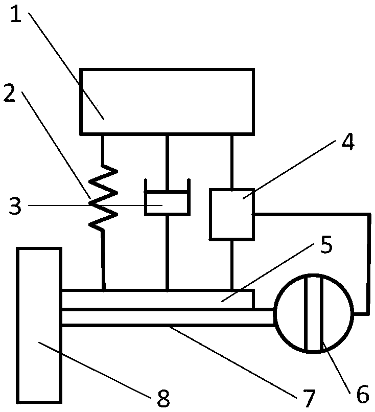
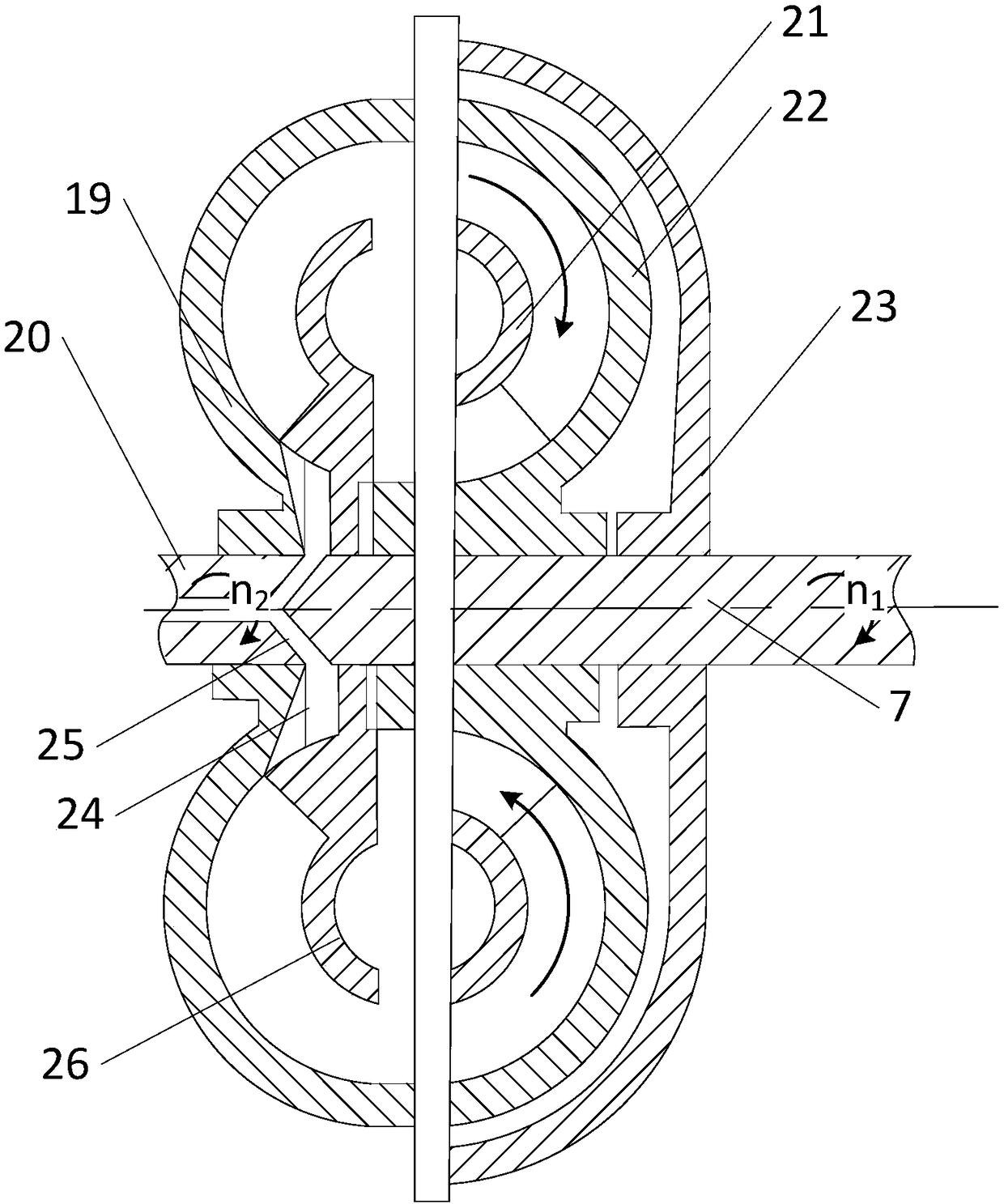
[0024] like figure 1 As shown, the suspension vibration energy driven braking system of the present invention includes an inerter assembly 4, a hydraulic motor coupling assembly 6 and a drive shaft 7; the inerter assembly 4, spring element 2 and damping element 3 are respectively installed on Between the vehicle body 1 and the swing arm 5; the hydraulic motor coupling assembly 6 includes a hydraulic motor 18 and a coupler assembly, the input transmission shaft 20 of the hydraulic motor 18 is connected to the coupler assembly, and the output end of the coupler assembly is connected to the drive shaft 7 for torque transmission; the drive shaft 7 is connected with the wheel 8.

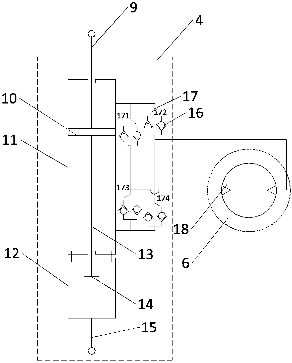
[0025] like figure 2 As shown, the container assembly 4 includes a double piston rod cylinder ...


PUM


Abstract

The invention provides a suspension vibration energy driving and braking system, including an inerter assembly, a hydraulic motor coupling assembly, and a driving shaft. The inerter assembly is arranged between a vehicle body and a swing arm. The hydraulic motor coupling assembly comprises a hydraulic motor and a coupling assembly. An input transmission shaft of the hydraulic motor is connected with the coupling assembly. An output end of the coupling assembly is connected with the driving shaft, used to transmit torque. The inerter assembly comprises a double piston-rod cylinder and a one-wayvalve assembly. The one-way valve assembly comprises one-way valves and a change-over switch. The two one-way valves are connected in parallel, and the installation directions of the two one-way valves are opposite. The two one-way valves are connected with the change-over switch. The system can directly convert vibration energy of a vehicle to driving energy or braking energy, so that energy isnot needed to be converted repeatedly. The system has higher efficiency, and can recycle vibration energy to the maximum extent, to achieve an objective of energy conservation and emission reduction for vehicles.

Description

technical field [0001] The invention relates to the technical field of vehicle suspension, in particular to a suspension vibration energy driven braking system. Background technique [0002] In recent years, energy conservation and emission reduction in various industries has become a very important issue. One available method of limiting energy dissipation is to reclaim that dissipated energy. During the driving process of the vehicle, the unevenness of the road surface and the acceleration and deceleration of the vehicle will cause the relative displacement of the sprung mass and the unsprung mass of the vehicle, thereby generating a certain amount of vibration energy. Due to the existence of passive shock absorbers in traditional suspensions, This part of the vibration energy will be dissipated into the atmosphere in the form of heat and lost. At present, the commonly used method is to use a motor (linear motor or rotary motor) to convert the mechanical energy of vibrat...

Claims


Application Information

Patent Timeline
Patent Type & Authority Applications(China)
IPC IPC(8): F03G7/08B60K25/10
CPCB60K25/10B60K2025/106F03G7/08
Inventor 陈龙刘昌宁杨晓峰杨艺刘雁玲沈钰杰李洪昌赵文涛
Owner JIANGSU UNIV
Why Eureka
Eureka Blog
Learn More