Shock absorber piston valve structure

A technology for piston valves and shock absorbers, applied in the direction of shock absorbers, shock absorbers, springs/shock absorbers, etc., can solve problems such as complex assembly relationships, cavitation, cavitation, etc., to improve stability and Reliability, reduction of cavitation phenomenon, effects of avoiding empty space phenomenon

Inactive Publication Date: 2018-08-31
YANGZHOU UNIV
View PDF10 Cites 1 Cited by
  • Summary
  • Abstract
  • Description
  • Claims
  • Application Information

AI Technical Summary

Problems solved by technology

[0004] However, this device has the following disadvantages: structurally, the device has many parts and complex assembly relations, and the structure of the piston valve spool is complex and difficult to process and manufacture; at the same time, the shock absorber will produce voids at high speeds. When the piston rod moves and turns, the damping force will appear empty. Therefore, the damping force cannot be provided under these special working conditions, which will cause the damping effect to deteriorate; the most important factor affecting the damping characteristics of the shock absorber is its spool. The damping force generated by the coupling between the structure and the oil. In the past, the shock absorber used the throttling pressure generated by the oil flowing through the throttling hole and the throttling gap to make the shock absorber have a throttling damping force. The damping force effect, the throttle holes and the throttle gaps are generally small. At high speed, when the oil moves from the high-pressure chamber to the low-pressure chamber through these throttle holes and throttle gaps, the oil replenishment will not be timely Therefore, the working characteristics of the shock absorber are distorted, which affects the vibration reduction effect. At the same time, due to the small throttle hole and the throttle gap, the oil flows through it at a faster speed, resulting in a sharp drop in oil pressure. , which will cause cavitation, and then cavitation, which will affect the service life of the shock absorber

Method used


Image

  • Shock absorber piston valve structure
  • Shock absorber piston valve structure
  • Shock absorber piston valve structure

Examples


Embodiment Construction

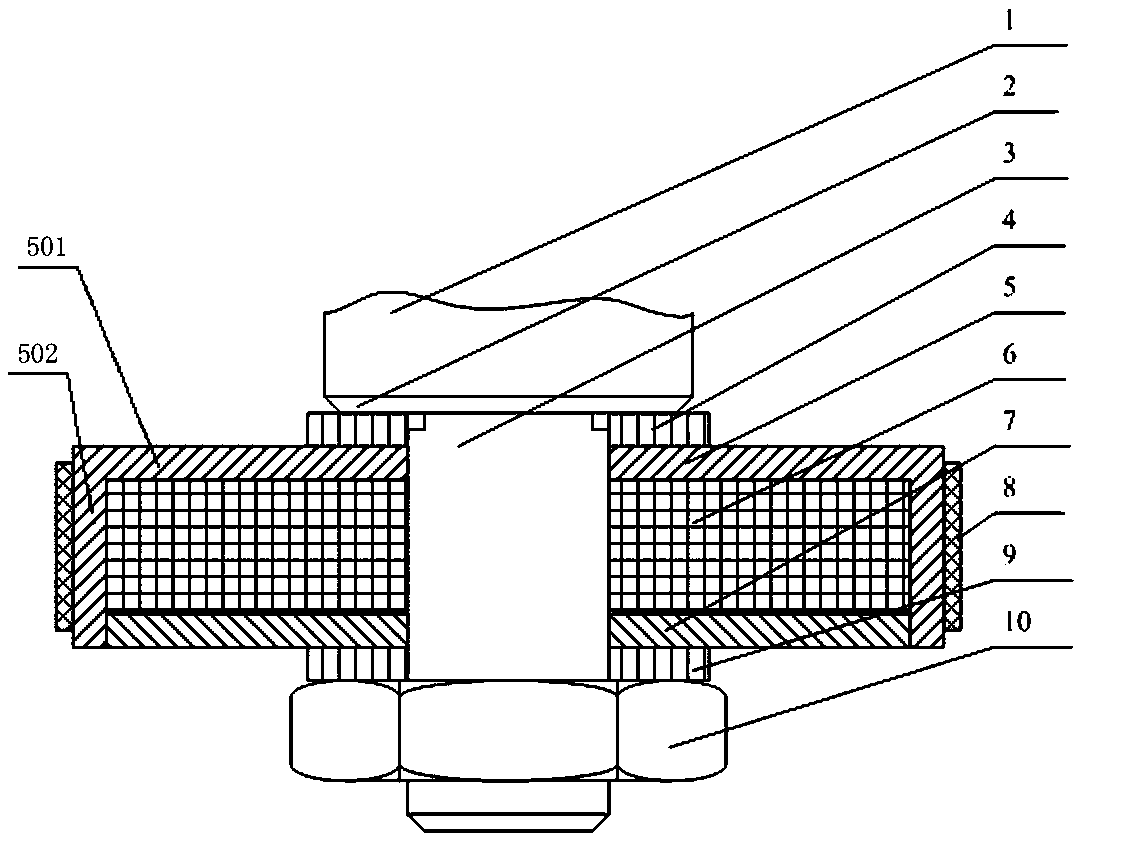
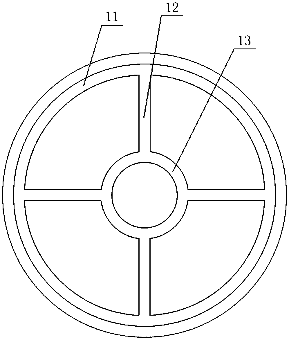
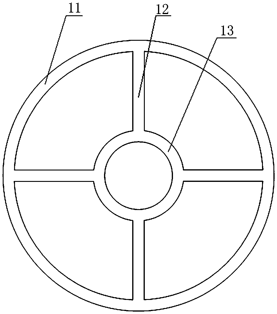
[0019] Such as Figure 1-3 As shown, it is a shock absorber piston valve structure, including a piston rod composed of a coaxial large-diameter section and a journal section. A piston valve is provided on the journal section 1 of the piston rod, and the piston valve includes a sleeve set on The spool 6 on the journal section 3 of the piston rod is made of porous material. The spool 6 is provided with a number of through-holes that communicate with each other, and the oil chambers located above and below the spool 6 can be connected through the through-holes. The valve core 6 is provided with a covering body 5 covering the valve core 6 , and the upper side and the lower side of the covering body 5 are provided with a plurality of through holes axially penetrating through the covering body 5 . The porous material is metal rubber, metal porous material, open foam aluminum or porous ceramic material. The valve core 6 is composited by one or more of the above-mentioned porous mate...


PUM


Abstract

The invention discloses a shock absorber piston valve structure, and relates to the field of shock absorbers. The shock absorber piston valve structure comprises a piston rod which is composed of a coaxial large-diameter section and journal section; a piston valve is arranged on the journal section of the piston rod and comprises a valve element which sleeves the journal section of the piston rod;the valve element is made of a porous material; a plurality of through holes I communicating with one another are formed in the valve element; oil cavities which are formed in the upper part and thelower part of the valve element separately can communicate with each other through the through holes I; a covering body covering the valve element is arranged on the valve element; and a plurality ofthrough holes II penetrating through the covering body in the axial direction are formed in the upper side and the lower side of the covering body. According to the shock absorber piston valve structure, the porous material is applied to a valve element structure of the shock absorber piston valve, irregular pore microstructures inside the porous material are utilized, so that energy dissipation is generated when compressed oil liquid flows through the pore microstructures, and damping force is generated; and a large number of pore structures on the surface of the porous material are utilized,the contact area of the porous material and the upper oil cavity and the lower oil cavity is increased, and therefore under the high-speed working condition, and the phenomena that the working characteristics of the shock absorber are distorted, and cavitation of the oil liquid is generated can be avoided.

Description

technical field [0001] The invention belongs to the field of shock absorbers, in particular to a piston valve structure of a shock absorber. Background technique [0002] Shock absorbers in motor vehicles are usually in the form of hydromechanical shock absorbers and are used here in particular between the respective frame and axle of the respective motor vehicle. The shock absorber is then used at this location on the one hand to prevent swaying and vibrations of the vehicle frame when excited by the roadway or in certain driving situations and on the other hand to achieve rapid damping of the wheels by Vibration excited by the roadway. In the last-mentioned case, the road adhesion of the wheel is thus always guaranteed. [0003] In the prior art, there is a shock absorber and a piston valve used for the shock absorber, its patent application number: 201480074437.8; application date: 2014.12.17; publication number: CN 105940238 A; publication date: 2016.09. 14; its struc...

Claims


Application Information

Patent Timeline
Patent Type & Authority Applications(China)
IPC IPC(8): F16F9/34
CPCF16F9/3405
Inventor 李竞关栋沈辉凌曦韦梦圆黄庆华王永任宪奇高悦文
Owner YANGZHOU UNIV
Why Eureka
Try Eureka