Optics lens and assembly method and lens barrel thereof

一种光学镜头、组装方法的技术,应用在光学、光学元件、安装等方向,能够解决影响光学镜片于镜筒排列、固定环移动或脱落、溶融状态不平均等问题,达到增加黏固成效、降低固定环偏斜、间隙平均的效果

Active Publication Date: 2018-08-31
GENIUS ELECTRONICS OPTICAL XIAMEN
View PDF17 Cites 3 Cited by
  • Summary
  • Abstract
  • Description
  • Claims
  • Application Information

AI Technical Summary

Problems solved by technology

However, since the contact surfaces between the lens barrel and the fixed ring are all smooth surfaces, and the fixed ring is prone to deflection when the fixed ring is assembled on the lens barrel, the gaps between the fixed ring and the lens barrel are of different sizes, and The melting state of each point between the fixing ring and the lens barrel is uneven
The joining strength of this method is not enough, and the fixing ring is easy to move or fall off from the lens barrel, which affects the arrangement of the optical lens in the lens barrel, or even disintegrates the lens

Method used


Image

  • Optics lens and assembly method and lens barrel thereof
  • Optics lens and assembly method and lens barrel thereof
  • Optics lens and assembly method and lens barrel thereof

Examples


Embodiment Construction

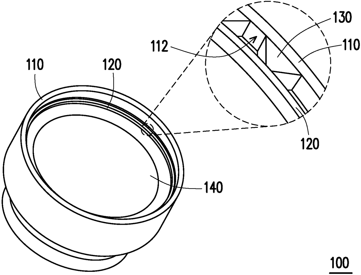
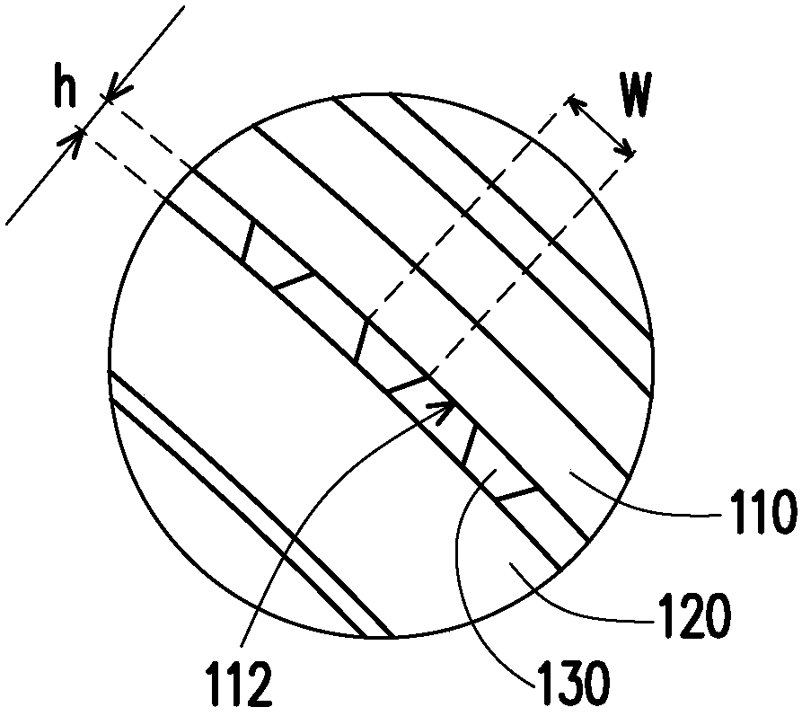
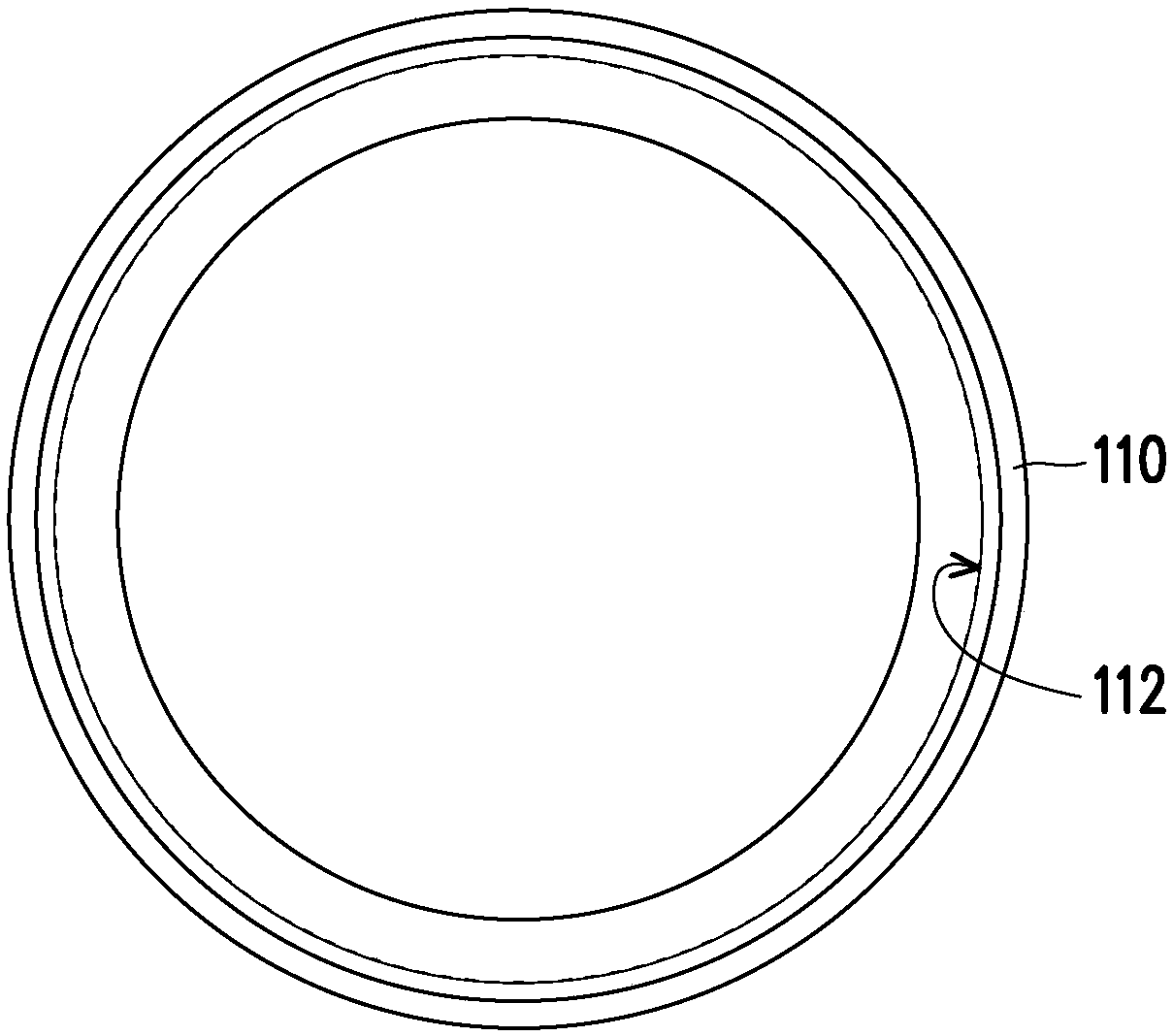
[0020] Figure 1A is a stereoscopic schematic diagram of an optical lens according to an embodiment of the present invention, Figure 1B yes Figure 1A The partial cross-sectional schematic diagram of the optical lens, Figure 2A yes Figure 1A Schematic diagram of the rear view of the lens barrel and optical lens, Figure 2B yes Figure 2A Schematic diagram of the cross-section of the lens barrel and optical lens, Figure 3A yes Figure 1A The three-dimensional schematic diagram of the fixed ring, and Figure 3B yes Figure 1A A schematic cross-sectional view of the retaining ring. Figure 4 yes Figure 1A Schematic diagram of the cross-section of the optical lens. Please refer to Figure 1A to Figure 3B The optical lens 100 of this embodiment includes a lens barrel 110 , a fixing ring 120 and at least one optical lens 140 (a plurality of optical lenses 140 are taken as an example in this embodiment). The lens barrel 110 has a joint surface 112 along the inner side of t...


PUM


Abstract

The invention discloses an optics lens including a lens barrel, a fixing ring and at least one optics lens element. A joint surface is arranged along the inner edge of one end of the lens barrel. Thejoint surface is provided with a plurality of microstructures arranged on a circle. The microstructures are convex on the joint surface. The fixing ring is arranged in the joint surface of the lens barrel. The optics lens elements are arranged in the lens barrel. The microstructures and the fixing ring on the joint surface are dissolved by using a solvent to fixedly arrange the optics lens elements in the lens barrel. Furthermore, the invention also provides an assembly method and lens barrel of the optics lens. The optics lens with high reliability and durability can be manufactured accordingto the invention.

Description

technical field [0001] The present invention relates to an optical element and its assembly method, and in particular to an optical lens, its assembly method and lens barrel. Background technique [0002] Optical lens In order to fix the optical lens in the lens barrel, a fixing ring is placed on the outermost side of the optical lens, and then a solvent point is placed between the joint surface of the lens barrel and the fixing ring to make it fused. However, since the contact surfaces between the lens barrel and the fixed ring are all smooth surfaces, and the fixed ring is prone to deflection when the fixed ring is assembled on the lens barrel, the gaps between the fixed ring and the lens barrel are of different sizes, and The melting state of each point between the fixing ring and the lens barrel is uneven. The joining strength of this method is not enough, and the fixing ring is easy to move or fall off from the lens barrel, which affects the arrangement of the optical ...

Claims


Application Information

Patent Timeline
Patent Type & Authority Applications(China)
IPC IPC(8): G02B7/02
CPCG02B7/025G02B7/026
Inventor 林嘉铭陈郁茗庄家维
Owner GENIUS ELECTRONICS OPTICAL XIAMEN
Why Eureka
Try Eureka