Laser light source

A technology of laser light source and laser beam, applied in optics, optical components, instruments, etc., can solve the problems of energy transmission efficiency reduction

Inactive Publication Date: 2018-08-31
CHANGCHUN INST OF OPTICS FINE MECHANICS & PHYSICS CHINESE ACAD OF SCI
8 Cites 5 Cited by

AI-Extracted Technical Summary

Problems solved by technology

However, when the target system (that is, the system that receives laser energy) is a moving target (for example, a drone or a space spacecraft, etc.), the distance between the laser source and the target system generally changes, and...

Abstract

The invention discloses a laser light source. The light source comprises a controller, a laser emitter and a laser light beam adjusting device. The laser emitter and the laser light beam adjusting device are connected with the controller. The controller is used for controlling the laser emitter to emit laser light beams and controlling the laser light beam adjusting device so as to change emissionangles of the laser light beams to allow the light spot size of the laser light beams on the target unit to match the size of the target unit according to the laser transmission distance between thelaser light source and a target unit. According to the invention, when energy transmission is performed on the movement target, the emission angles of the emitted-out laser light beams are adjusted according to the laser transmission distance between the laser light beams and the target unit so as to allow the light spot size of the laser light beams to match the size of the target unit, and the energy transmission efficiency is stable.

Application Domain

Optical elements

Technology Topic

Laser lightOptoelectronics +4

Image

  • Laser light source
  • Laser light source
  • Laser light source

Examples

  • Experimental program(1)

Example Embodiment

[0027] The technical solutions in the embodiments of the present invention will be clearly and completely described below in conjunction with the accompanying drawings in the embodiments of the present invention. Obviously, the described embodiments are only a part of the embodiments of the present invention, rather than all the embodiments. Based on the embodiments of the present invention, all other embodiments obtained by those of ordinary skill in the art without creative work shall fall within the protection scope of the present invention.
[0028] In order to make the above objectives, features and advantages of the present invention more obvious and understandable, the present invention will be further described in detail below with reference to the accompanying drawings and specific embodiments.
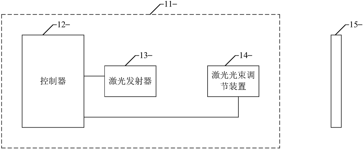
[0029] reference figure 1 , figure 1 This is a schematic structural diagram of a laser light source provided by an embodiment of the present invention.
[0030] The laser light source 11 includes: a controller 12, a laser transmitter 13 and a laser beam adjusting device 14; wherein the laser transmitter 13 and the laser beam adjusting device 14 are respectively connected to the controller 12.
[0031] The controller 12 is used to control the laser transmitter 13 to emit a laser beam; the controller 12 is also used to control the laser beam adjusting device according to the laser transmission distance between the laser light source 11 and the target unit 15 14. To change the divergence angle of the laser beam so that the spot size of the laser beam on the target unit 15 matches the size of the target unit 15.
[0032] Specifically, when the laser light source 11 starts to work, the controller 12 drives the laser transmitter 13 to emit a laser beam of a certain wavelength and a certain power, and passes through the laser beam adjusting device 14 to change the divergence angle of the laser beam to make the laser beam The spot size of the light beam on the target unit 15 matches the size of the target unit 15. It should be noted that the laser light source 11 can design the laser divergence angle variation range according to the laser transmission distance range to ensure that the laser light source 11 meets various different usage scenarios.
[0033] Optionally, the laser transmitter 13 includes but is not limited to a semiconductor laser, which is not limited in the embodiment of the present invention.
[0034] Further, based on the foregoing embodiment of the present invention, in another embodiment of the present invention, such as figure 2 As shown, the laser light source 11 further includes: a real-time distance measuring device 16.
[0035] Wherein, the real-time distance measuring device 16 is connected to the controller 12 and is used to obtain the laser transmission distance between the laser light source 11 and the target unit 15 in real time.
[0036] Specifically, when the controller 12 drives the laser transmitter 13 to emit a laser beam of a certain wavelength and a certain power, the real-time ranging device 16 starts to work, and obtains the real-time distance between the laser light source 11 and the target unit 15 Laser transmission distance, that is, energy transmission distance.
[0037] Further, based on the foregoing embodiment of the present invention, in another embodiment of the present invention, such as image 3 As shown, the laser beam adjusting device 14 includes: a beam expander lens 17 and a displacement stage 18.
[0038] Wherein, the displacement stage 18 is connected to the controller 12, the beam expander lens 17 is mounted on the displacement stage 18, and the laser transmitter 13 and the beam expander lens 17 are located on the same axis.
[0039] The controller 12 controls the displacement stage 18 to adjust the distance between the beam expander lens 17 and the laser generator 13 according to the laser transmission distance to change the divergence angle of the laser beam, so that the laser The spot size of the light beam on the target unit 15 matches the size of the target unit 15.
[0040] Specifically, when the controller 12 drives the laser transmitter 13 to emit a laser beam of a certain wavelength and a certain power, the real-time ranging device 16 starts to work, and obtains the real-time distance between the laser light source 11 and the target unit 15 Laser transmission distance, the controller 12 controls the displacement stage 18 to adjust the position of the beam expander lens 17 in real time according to the laser transmission distance, thereby changing the divergence angle of the laser beam, and finally ensuring the spot on the moving target unit 15 The size matches the size of the target unit 15.
[0041] It should be noted that in this field, the target unit 15 includes but is not limited to a photovoltaic panel.
[0042] Optionally, the displacement stage 18 is an automatic adjustment electric displacement stage, which realizes a laser light source with an automatically adjustable laser divergence angle.
[0043] Further, based on the above-mentioned embodiments of the present invention, in another embodiment of the present invention, a sliding track is provided on the displacement platform 18.
[0044] Wherein, the beam expander lens 17 is installed on the sliding track, and the controller 12 controls the displacement stage 18 to drive the beam expander lens 17 to move on the sliding track.
[0045] Specifically, the displacement platform 18 is provided with a sliding track, and the beam expander lens 17 is fixed by a sliding device, and then is arranged on the slide track so that the beam expander lens 17 can move on the slide track.
[0046] Further, based on the foregoing embodiment of the present invention, in another embodiment of the present invention, such as Figure 4 As shown, the laser light source 11 further includes: a fast and slow axis compression lens 19.
[0047] Wherein, the fast and slow axis compression lens 19 is arranged between the laser transmitter 13 and the beam expander lens 17 for changing the angle of the fast axis direction and the slow axis direction of the laser beam.
[0048] Specifically, after the controller 12 drives the laser transmitter 13 to emit a laser beam with a certain wavelength and a certain power, the laser beam first passes through the fast and slow axis compression lens 19 to change the angle between the fast axis direction and the slow axis direction of the laser beam In order to improve the beam quality, the laser beam adjusting device 14 adjusts the divergence angle of the laser beam so that the spot size of the laser beam on the target unit 15 matches the size of the target unit 15.
[0049] Based on all the foregoing embodiments of the present invention, specific implementation scenarios are used as an example for description.
[0050] Implementation scenario environment: For example, the laser transmission distance is 500 meters to 1000 meters, and the target unit photovoltaic panel is installed on the bottom surface of the drone wing with a diameter of about 30 cm.
[0051] Based on the above implementation scenario environment, when a laser light source with a fixed divergence angle is used, if the distance between the laser light source and the target unit photovoltaic panel is 500 meters, the spot size of the laser beam on the target unit photovoltaic panel is equal to that of the target unit photovoltaic panel. If the size is matched, when the distance between the laser light source and the target unit photovoltaic panel is 1000 meters, the energy density is reduced to 25%, and 75% of the transmission energy is lost; if the distance between the laser light source and the target unit photovoltaic panel is When it is 1000 meters, the spot size of the laser beam on the target unit photovoltaic panel matches the size of the target unit photovoltaic panel. Then, when the distance between the laser light source and the target unit photovoltaic panel is 500 meters, the laser beam is in the target unit The size of the light spot on the photovoltaic panel is only 25% of the area of ​​the photovoltaic panel, which can easily cause local overheating and burnout. The remaining 75% of the photovoltaic panels not only cannot generate electricity, but also become a power-consuming load.
[0052] Based on the foregoing implementation scenario environment, the laser light source provided by the embodiment of the present invention is used, for example, the coverage range of the divergence angle of the laser beam determined by a beam expander lens with a diameter of 10 cm and a fast and slow axis compression lens is 0.1 mrad-0.2 mrad. When the real-time ranging device measures the distance between the laser light source and the target unit photovoltaic panel is 1000 meters, the controller adjusts the position of the beam expander lens on the translation stage to reduce the divergence angle of the laser beam to 0.1mrad. At this time, the laser The spot size of the beam on the target unit photovoltaic panel is about 30cm, which basically matches the size of the target unit photovoltaic panel; when the drone moves, the real-time ranging device measures the distance between the laser light source and the target unit photovoltaic panel as 500 meters At this time, the controller adjusts the position of the beam expander lens on the translation stage to increase the divergence angle of the laser beam to 0.2mrad. At this time, the spot size of the laser beam on the target unit photovoltaic panel is about 30cm, which is basically the same as the target unit photovoltaic cell. The size of the board matches; when the UAV is moving, the real-time ranging device measures the distance between the laser light source and the target unit photovoltaic panel to be between 500 meters and 1000 meters, the controller adjusts the beam expander lens on the platform The position of the laser beam to make the divergence angle of the laser beam to a value between 0.1mrad-0.2mrad. At this time, the spot size of the laser beam on the target unit photovoltaic panel is about 30cm, which is basically the same as the size of the target unit photovoltaic panel match.
[0053] It can be seen from the above description that the laser light source provided by the present invention can adjust the divergence angle of the emitted laser beam according to the laser transmission distance between the laser light source and the target unit in real time when transmitting energy to a moving target. The spot size of the laser beam on the target unit is matched with the size of the target unit, and the energy transmission efficiency is stable.
[0054] The foregoing description of the disclosed embodiments enables those skilled in the art to implement or use the present invention. Various modifications to these embodiments will be obvious to those skilled in the art, and the general principles defined in this document can be implemented in other embodiments without departing from the spirit or scope of the present invention. Therefore, the present invention will not be limited to the embodiments shown in this text, but should conform to the widest scope consistent with the principles and novel features disclosed in this text.

PUM

no PUM

Description & Claims & Application Information

We can also present the details of the Description, Claims and Application information to help users get a comprehensive understanding of the technical details of the patent, such as background art, summary of invention, brief description of drawings, description of embodiments, and other original content. On the other hand, users can also determine the specific scope of protection of the technology through the list of claims; as well as understand the changes in the life cycle of the technology with the presentation of the patent timeline. Login to view more.
Why Eureka
Try Eureka