Integrated controlling and remote monitoring platform for connected vehicle
A vehicle control and remote monitoring technology, applied in program control, general control system, electrical testing/monitoring, etc., can solve the problems such as the inability of the vehicle terminal to interact with the vehicle controller, vehicle performance evaluation, and poor operation timeliness, etc. The effect of reducing data processors, good operation timeliness, and increasing monitoring variables
Inactive Publication Date: 2018-08-31
TIANJIN UNIV
4 Cites 13 Cited by
AI-Extracted Technical Summary
Problems solved by technology
At present, there are still the following limitations in the field of vehicle controllers and on-board monitoring systems in the automotive industry: First, the current vehicle controllers on the market are installed inside the car, which is troublesome to disassemble and assemble, and requires engineers to come to the site for real vehicle testing , poor operational timeliness
Second, it is impossible to remotely calibrate and diagnose the vehicle controller
During the actual vehicle test of the vehicle controller, mechanical disassembly and assembly are required to obtain the running status of the vehicle, and manual on-site operation is performed for diagnosis and calibration, resulting in low work efficiency
Third, t...
Method used
[0027] The disclosure provides a vehicle control and remote monitoring platform for intelligent networking, the vehicle control and remote monitoring platform includes a vehicle control module, a remote monitoring host computer module and a vehicle-mounted intelligent hardware module, the vehicle control module Used for the operation of the overall management system, real-time collection of signals sent by peripheral sensors and/or information interaction with external devices, and control of the vehicle through the vehicle control module; the vehicle-mounted intelligent hardware module is used in the vehicle control module and remote Information exchange between the monitoring host computer modules; the vehicle intelligent hardware module and the vehicle control module share the microcontroller; the remote monitoring host computer module is used to monitor, locate and/or data analyze the vehicle according to the interactive information of the vehicle intelligent hardware module . Based on the vehicle control and remote monitoring platform, the present disclosure integrates vehicle networking functions based on GPRS/3G, Bluetooth, GPS positioning, etc., which can not only realize the vehicle control function, but also realize remote data transmission, remote monitoring and calibration, etc. This function gives full play to the advantages of the vehicle controller and remote monitoring terminal, and then develops an intelligent network connection, vehicle control and remote monitoring platform hardware platform for hybrid vehicles, pure electric vehicles and other new sources of vehicles , The application market has a great prospect.
[0035] The communication module is used for information interaction with external equipment, and the communication module includes: a CAN communication module, a serial port communication module and an Ethernet communication module. CAN communication module is used for vehicle control module and vehicle intelligent hardware module to share information with other external devices through CAN bus. The CAN communication module here can choose Infineon's automotive-grade CAN transceiver chip TLE6250G, which has low power consumptio...
Abstract
The invention discloses an integrated controlling and remote monitoring platform for connected vehicle, which comprises a vehicle controlling module, a vehicle-mounted smart device, and a remote monitoring upper computer module. The controlling module is used for running the overall management system, receiving signals sent by the peripheral sensors in real time and/or carrying out information interaction with the external devices, and controlling the vehicle; the vehicle-mounted smart device is used for carrying out information interaction between the controlling module and the remote monitoring upper computer module; the vehicle-mounted smart device and the vehicle controlling module share a microcontroller; the remote monitoring upper computer module is used for monitoring, locating and/or data analyzing of the vehicle according to the interaction information of the vehicle-mounted smart device. The invention has the features of data collection, fault diagnosis, remote calibration,OTA system upgrade and background unified management through GPRS/3G wireless communication and remote service with less maintenance and high efficiency.
Application Domain
Programme controlElectric testing/monitoring
Technology Topic
Real time acquisitionE communication +10
Image
Examples
- Experimental program(1)
Example Embodiment
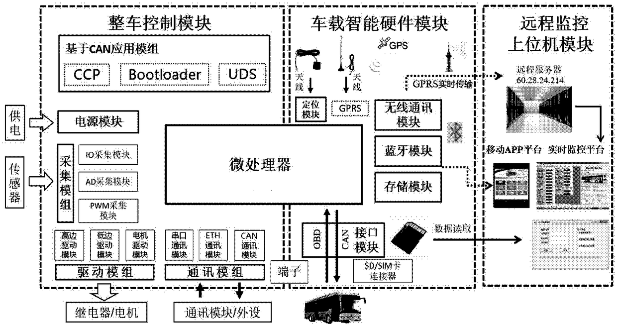
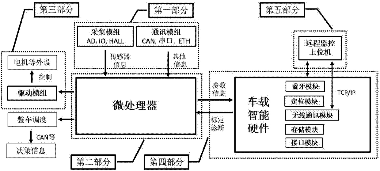
[0027] The present disclosure provides a vehicle control and remote monitoring platform for intelligent network connection. The vehicle control and remote monitoring platform includes a vehicle control module, a remote monitoring host computer module, and a vehicle intelligent hardware module. The vehicle control module is used for the whole Manage the operation of the system, collect signals sent by peripheral sensors in real time and/or exchange information with external equipment, and control the entire vehicle through the vehicle control module; the vehicle intelligent hardware module is used to monitor the entire vehicle control module and remotely monitor the upper computer Information interaction between the modules; the on-board intelligent hardware module and the vehicle control module share a microcontroller; the remote monitoring host computer module is used to monitor, locate and/or analyze the entire vehicle based on the interactive information of the on-board intelligent hardware module. On the basis of the vehicle control and remote monitoring platform, this disclosure integrates vehicle networking functions based on GPRS/3G, Bluetooth, GPS positioning, etc., which can realize vehicle control functions, as well as remote data transmission, remote monitoring and calibration, etc. This function makes full use of the advantages of the vehicle controller and remote monitoring terminal, and then develops a hardware platform for intelligent network connection and vehicle control and remote monitoring platform for hybrid vehicles, pure electric vehicles and other new source vehicles , The application market has great prospects.
[0028] In order to make the objectives, technical solutions, and advantages of the present disclosure clearer, the following further describes the present disclosure in detail with reference to specific embodiments and drawings.
[0029] Certain embodiments of the present disclosure will be described more fully in the following with reference to the accompanying drawings, and some but not all of the embodiments will be shown. In fact, the various embodiments of the present disclosure can be implemented in many different forms, and should not be construed as being limited to the embodiments described in this number; relatively, the provision of these embodiments enables the present disclosure to meet applicable legal requirements.
[0030] In an exemplary embodiment of the present disclosure, a vehicle control and remote monitoring platform for intelligent network connection is provided. figure 1 This is a schematic structural diagram of a vehicle control and remote monitoring platform for intelligent network connection in an embodiment of the present disclosure. Such as figure 1 As shown, the vehicle control and remote monitoring platform of the present disclosure includes: a vehicle control module, a vehicle intelligent hardware module, and a remote monitoring host computer module.
[0031] The vehicle control module is used for the operation of the overall management system, collects signals sent by peripheral sensors and/or interacts with external equipment in real time, controls the vehicle through the vehicle control module, and controls the vehicle through CAN communication. The remote monitoring platform performs program flashing, calibration and fault diagnosis. The vehicle control module and the vehicle intelligent hardware module share a microcontroller. The vehicle control module includes: power module, acquisition module, communication module, drive module and CAN-based application module. The vehicle control module and the vehicle intelligent hardware module share a microcontroller.
[0032] For the microcontroller, you can choose the latest Aurix TriCore series microcontroller from Infineon Semiconductor, the model is SAK-TC275TP-64F200W automotive-grade microcontroller. TC275 is a 32-bit microcontroller integrated with 3 CPUs, and its 3 CPUs can be It runs independently at the same time. It integrates up to 4MByte Flash and GTM and other special modules on-chip. The operating frequency can reach 200MHz. It has a wealth of pins, including AD pins, ordinary IO pins, PWM acquisition pins, PWM output pins, CAN communication pins, QSPI communication pins, serial communication pins, etc., to meet the needs of vehicle control. The power module regulates the voltage of the external battery from 8V to 48V to 5V or 3.3V for the power management module of the microcontroller. In addition, it also includes a clock circuit, a JTAG circuit, and a basic configuration pin circuit.
[0033] The power module is used to supply power to the microcontroller and the modules of the vehicle control and remote monitoring platform, such as the microcontroller, Bluetooth module, etc. At the same time, the power module can also be equipped with ESD protection, reverse connection protection, overvoltage protection, and undervoltage protection to ensure that the system can work in the electrical environment of the car load. Here, the power supply module can use Infineon’s TLE7368-3E. The vehicle power supply 24V supplies power to the power supply module. It outputs 5V, 3.3V and 1.3V voltages through diodes and filter circuits to supply power to other modules in the vehicle control and remote monitoring platform.
[0034] The acquisition module is used to acquire the signals sent by the peripheral sensors. The acquisition module includes: IO acquisition module, AD acquisition module and PWM acquisition module. The IO acquisition module is used to collect external switch signals; the IO signals are supplied to the microcontroller for sampling after ESD protection voltage division, current limiting and overvoltage protection. The circuit can be designed as high-level active or low-level active according to different applications At the same time, it can be flexibly configured for different switch input signal levels. The AD acquisition module is mainly used to properly adjust the external analog signal to meet the scope of the microcontroller acquisition. These adjustments include range conversion, filtering, overcurrent and overvoltage protection, etc., specifically for different sensor input types, which can be flexibly configured as voltage sensors, resistance sensors, etc., or according to the resistance or voltage value of the sensor The scope is flexibly configured. The PWM acquisition module is used to process the PWM signal received from the external Hall sensor; after ESD protection voltage division, current limiting and overvoltage protection, it is compared with the voltage comparator, and the comparison result is supplied to the microcontroller for sampling; for different sensors The input type can be flexibly configured with different Hall signal types, and it can also be configured flexibly according to the resistance or voltage value range of the sensor.
[0035] The communication module is used for information interaction with external equipment. The communication module includes: CAN communication module, serial communication module and Ethernet communication module. CAN communication module is used for vehicle control module and vehicle intelligent hardware module to share information with other external devices via CAN bus. Here, the CAN communication module can be selected from Infineon's automotive CAN transceiver chip TLE6250G, which has low power consumption, and has a very strong anti-interference ability and over-temperature protection. The MultiCAN module inside the TC275 microcontroller has the function of a CAN controller. You only need to configure a CAN transceiver externally to complete the construction of the CAN communication module. The serial port communication module is used for the vehicle control module and the vehicle intelligent hardware module to communicate with external devices through the serial port. The RS232 serial communication module can be selected here. The RS232 serial communication module adopts the MAX232 chip design, which can realize the conversion between the external RS232 level and the TTL level of the microcontroller, for the microcontroller and peripherals to communicate through the serial port, or directly The TTL level is output through the serial port of the microcontroller, which realizes the configurability of RS232 and TTL levels. The Ethernet communication module is used for data interaction between the vehicle control module and the vehicle intelligent hardware module and external equipment via Ethernet. Here the Ethernet communication module adopts KSZ8081RNB chip design, and the Ethernet interface adopts standard RJ45. Its transmission data is much larger than that of serial port, CAN and other transmission methods. It can interact with external GPU and FPGA, and can also realize functions such as calibration.
[0036] The drive module is used to drive relays and/or motors to control the entire vehicle. Drive modules include: high-side drive modules, low-side drive modules and motor drive modules. The high-side drive module is used to drive the external actuator according to the signal sent by the microcontroller. Here, the high-side drive module can include 4 channels, built with Infineon's BTS724G, and realize flexible control of power devices through PWM. At the same time, the chip integrates complete protection functions to achieve hardware failures such as overvoltage, overtemperature, open circuit, and short circuit. Detection. Mainly used to drive external actuators, such as some relays, solenoid valves, etc. The low-side drive module is used to drive the external actuator according to the signal sent by the microcontroller. Here, the low-side drive module can include 12 channels, built with Infineon’s TLE6240GP, and realizes flexible control of power devices through SPI. At the same time, the chip integrates complete protection functions, which can realize hardware failures such as overvoltage, overtemperature, open circuit, and short circuit. The detection is mainly used to drive external actuators, such as some relays, solenoid valves, etc. The motor drive module is used to drive the motor according to the signal sent by the microcontroller. It can also be divided into brushless DC motor drive modules and brushed DC motor drive modules. The brushless DC motor drive module can be designed with Allegro MicroSystems' A3930/3931KJPTR-T chip to meet 5V to 50V power supply, suitable for automotive 48V systems, including 3 HALL signal inputs, 1 PWM output, and 1 DIR (Direction) input. Its control methods mainly include internal closed-loop current control and external DIR and PWM control. An external three-phase bridge circuit is used to drive motors up to 90A. It can drive more types of brushless DC motors. The brushed DC motor drive module includes 2 channels, which can use Allegro MicroSystems’ A4940KLPTR-T chip. A4940KLPTR-T is a full-bridge controller used with N-channel power MOSFETs, especially for the use of high-power inductive loads (such as DC Brush motor) is designed for automotive applications and meets the power supply voltage range of 5.5 to 50V. An external H-bridge circuit is used to drive motors up to 90A. It can drive more types of brushed DC motors.
[0037] Based on the CAN application module, it is used for program flashing (Bootloader), parameter calibration (CCP) and fault diagnosis (UDS) on the vehicle control and remote monitoring platform through CAN communication.
[0038] Vehicle intelligent hardware module, the vehicle intelligent hardware module and the vehicle control module share a microcontroller; used to exchange information between the vehicle control module and the remote monitoring host computer module to realize vehicle positioning, remote data transmission, fault diagnosis, and status feedback And parameter calibration and other functions. Including wireless communication module, Bluetooth module, positioning module, interface module and storage module.
[0039] The wireless communication module exchanges information with the remote monitoring host computer module through the GPRS/3G network. Here, the wireless communication module can use the SIM808 chip of SIMCOM, which supports communication in four frequency bands: 800/900/1800/1900MHZ, GPRS grade is 10, and the allowable rate is as high as 14,400bps. This module can realize the communication function of the car network, upload the latitude and longitude, engine speed, fuel consumption and other variables obtained by the vehicle control module and the vehicle intelligent hardware module to the remote monitoring host computer module to realize the remote monitoring of the vehicle status. In addition, the remote server can realize the functions of remote calibration and fault diagnosis of the vehicle control module and the vehicle intelligent hardware module through the remote monitoring of the host computer module.
[0040] The Bluetooth module exchanges information with the mobile APP platform through the Bluetooth module. Here the bluetooth module can adopt BLK-MD-BC04-B module design, communicate with the single-chip microcomputer through UART, and obtain all the information of the whole vehicle control module and the intelligent hardware module of the vehicle. The microcontroller sends various parameter information to the bluetooth module, Then the Bluetooth module sends the data to the mobile Bluetooth APP based on the SPP Bluetooth serial port protocol.
[0041] The positioning module obtains the vehicle position information in real time through the positioning module, and then transmits it to the remote monitoring host computer module through the wireless communication module, thereby real-time positioning and tracking of the vehicle. The positioning module here can use U-blox's NEO-6M-0-001 chip, up to 20 GPS channels can achieve simultaneous contact with 20 satellites, the positioning accuracy is 2.5m, and the distance resolution is 1cm. The data update rate is 1Hz, the maximum altitude is 18000m, and the maximum measurement speed is 1854kM/h. Can provide standard time, latitude and longitude, heading, altitude, magnetic declination and other parameters.
[0042] The interface module exchanges information with the vehicle intelligent hardware module through the interface module. Here, the interface module may include terminals, SD card connector module and SIM connector card module. The SD card connector can use Molex's 1040310811 model, which is a MiscroSD card connector, which takes up very little space and reduces the board space. The SIM card connector of the SIM card module can adopt the model 78646-3001 of molex company, which is a MiscroSIM card connector, which takes up a small space and is conducive to layout and wiring. It is mainly used in conjunction with the SIM808 module, by inserting Unicom, mobile, etc. SIM is used for data exchange based on GPRS/3G.
[0043] Storage module, through the storage module to store the acquired vehicle information data, support 8G/16G/32G capacity, the record data format can be binary storage or FAT32 format file system storage, can store any parameter information in the vehicle controller, Including sensor information, actuator information and control parameter information, the data can be downloaded by reading the SD card or wireless remotely.
[0044] The remote monitoring host computer module is used for monitoring, positioning and/or data analysis of the entire vehicle according to the interactive information of the vehicle-mounted intelligent hardware module. The remote monitoring host computer module includes a real-time monitoring platform and a mobile APP platform.
[0045] The real-time monitoring platform exchanges information with the vehicle-mounted intelligent hardware module through wireless communication. The real-time monitoring platform can receive the data sent from the vehicle control module and the vehicle intelligent hardware module through TCP/IP, generate a dynamic monitoring interface, display the driving parameter information of any monitored vehicle in real time, and can monitor some continuous parameters such as Current, voltage, vehicle speed, motor speed, etc. are drawn. The real-time monitoring platform has the function of flexibly setting the threshold of the specified monitoring volume. Once the data exceeds the designed threshold range, the software can give an alarm. In addition, this module has the read and write function of the Oracle database, which can write real-time data into the database immediately after processing, and the software has the function of historical data playback, which can record all parameters such as the driving track and operating parameters of each car For playback, the playback process can also be displayed on the map. In addition, the real-time monitoring platform can also send data to the vehicle controller through TCP/IP to realize the remote test and remote calibration of the vehicle controller.
[0046] The mobile APP platform monitors the working status of the vehicle through the data information obtained through information interaction with the vehicle intelligent hardware module. The mobile APP platform is based on the SPP Bluetooth serial port protocol to receive data from the Bluetooth module in the vehicle intelligent hardware module, which can monitor the working status of the vehicle, such as real-time monitoring of the vehicle speed, motor speed, battery SOC, and vehicle location. The location information is displayed on the map in real time, and other parameters can be displayed in the form of curves, dashboards or numbers. In addition, the fault query function can be realized.
[0047] figure 2 This is a schematic diagram of the hardware modules of the vehicle control and remote monitoring platform for intelligent network connection in the embodiments of the present disclosure. Such as figure 2 As shown, in this specific embodiment, it mainly includes: power supply module, micro-control module, IO acquisition module, AD acquisition module, PWM acquisition module, CAN communication module, CAN-based application module (including CAN_CCP/CAN_UDS/Bootloader), Ethernet communication module, serial communication module, high-side drive module, low-side drive module, brushless DC motor drive module, brushed DC motor drive module, GPRS/3G module, GPS module, Bluetooth module, SD card module, interface module And other modules.
[0048] image 3 This is a schematic diagram of the functional principle of the entire vehicle control and remote monitoring platform working mechanism for intelligent network connection in the embodiment of the present disclosure. Such as image 3 As shown, the vehicle control and remote monitoring platform includes five parts:
[0049] The first part includes the acquisition module and the communication module. In this part, the vehicle control module and the vehicle intelligent hardware module collect the signals sent by the peripheral sensors through the acquisition module; the communication module receives the CAN message in the CAN network through the CAN bus. Share information with external devices. The acquisition module also includes IO acquisition module, AD acquisition module and PWM acquisition module. The communication module also includes CAN communication module, serial communication module and Ethernet communication module.
[0050] The second part includes the microcontroller. The microcontroller of the vehicle control module and the vehicle intelligent hardware module receives variable information from the outside, performs signal analysis, filtering, etc., and uses the acquired parameters as the input of the vehicle control algorithm. The control strategy runs in the CPU to realize vehicle scheduling and decision-making, and outputs control signals through the function pins of the microcontroller. In addition, the microcontroller will use the sensor signals obtained by the vehicle control module and the vehicle intelligent hardware module and the variable information calculated by the control algorithm, and define the ID to share in the form of CAN messages. Other controllers will receive CAN messages as required, and The vehicle control module and the vehicle intelligent hardware module coordinate and control the vehicle together.
[0051] The third part includes drive modules, mainly including high-side drive modules, low-side drive modules and motor drive modules; the low-side drive module and high-side drive module receive PWM signals to control actuators such as relays and solenoid valves; motor drive modules Receive direction signals and PWM signals from the microcontroller to control high-power and high-current DC brushless motors and DC brushed motors.
[0052] The fourth part includes the vehicle intelligent hardware module, based on GPRS/3G, Bluetooth and other wireless communication to realize the information interaction between the vehicle controller and the remote monitoring host computer module. The vehicle-mounted intelligent hardware module includes a wireless communication module, a Bluetooth module, a positioning module, an interface module and a storage module.
[0053] The fifth part includes the remote monitoring upper computer module, mainly including real-time monitoring platform and mobile APP platform. The real-time monitoring platform receives the information sent from the controller through TCP/IP, performs vehicle status display, real-time positioning, data analysis, etc., and sends the parameter data that needs to be calibrated wirelessly to the controller for remote calibration. The real-time monitoring platform uses the map service provided by Google, which can provide two-dimensional, satellite, plane and satellite hybrid maps, and then analyze GPS latitude and longitude information for vehicle positioning, analyze vehicle speed, motor speed, etc. to display vehicle operating information in the form of dynamic windows; real-time After receiving the vehicle data information, the monitoring platform performs overall vehicle operation analysis, energy consumption statistical calculation, and mileage statistical analysis to realize simultaneous monitoring of multiple vehicles and single-vehicle tracking and monitoring. In addition, the mobile APP platform receives data sent from the controller based on Bluetooth wireless communication, analyzes according to the data transmission protocol, performs vehicle fault query and real-time monitoring of vehicle status, and can display vehicle location information on the map, with curves or dashboards, etc. The form displays parameter information such as vehicle speed and motor speed.
[0054] Figure 4 This is a flow chart of the working mechanism of the vehicle control and remote monitoring platform for intelligent network connection in the embodiment of the present disclosure. The working mechanism of this intelligent network-oriented vehicle control and remote monitoring platform is a method for intelligent network-oriented vehicle control and remote monitoring simultaneously. Such as Figure 4 As shown, the working mechanism of the whole vehicle control and remote monitoring platform for intelligent network connection includes:
[0055] Step A: Through the collection module and communication module in the vehicle control and remote monitoring platform, real-time collection of signals sent by peripheral sensors and interaction information with external devices are transmitted to the microcontroller through signal conditioning.
[0056] Step B: The microcontroller parses and processes the variable information from the outside, runs the vehicle control algorithm to output the control value, and shares the variable information obtained by the vehicle control and remote monitoring platform through CAN bus and other methods, and coordinates the control with other controllers. car.
[0057] Step C: The drive module of the vehicle control module drives the external actuator and/or motor according to the control signal sent by the microcontroller.
[0058] Step D: The vehicle intelligent hardware module realizes the information interaction between the vehicle controller and the remote monitoring host computer based on GPRS/3G, Bluetooth and other wireless communication.
[0059] Step E: The remote monitoring host computer module performs positioning, parameter monitoring, data statistical analysis, remote calibration and flashing of the entire vehicle based on the interactive information of the vehicle intelligent hardware module.
[0060] Figure 5 This is a schematic diagram of a real-time monitoring platform for an intelligent networked vehicle control and remote monitoring platform in an embodiment of the present disclosure. Such as Figure 5 Shown is the data information obtained through information interaction with the vehicle-mounted intelligent hardware module, and the generated monitoring interface can display the dynamic data of the monitored vehicle in real time.
[0061] Image 6 This is a schematic diagram of a mobile phone Bluetooth APP for an intelligent networked vehicle control and remote monitoring platform in an embodiment of the present disclosure. Such as Image 6 Shown is the use of Bluetooth communication with the vehicle-mounted intelligent hardware module to obtain the variable parameter information of the vehicle controller and monitor the vehicle driving status in real time.
[0062] So far, the embodiments of the present disclosure have been described in detail with reference to the accompanying drawings. It should be noted that, in the drawings or the main body of the specification, the implementation manners that are not shown or described are all forms known to those of ordinary skill in the art and are not described in detail. In addition, the above definitions of various elements and methods are not limited to the various specific structures, shapes or methods mentioned in the embodiments, and those of ordinary skill in the art can simply modify or replace them.
[0063] Based on the above description, those skilled in the art should have a clear understanding of the intelligent network-oriented vehicle control and remote monitoring platform of the present disclosure.
[0064] In summary, the present disclosure provides an intelligent networked vehicle control platform based on GPRS/3G and remote services to realize vehicle control, vehicle monitoring, fault diagnosis, parameter calibration, program upgrades, and unified background management, etc. Function, reduce personnel maintenance, high timeliness.
[0065] It should also be noted that the directional terms mentioned in the embodiments, such as "up", "down", "front", "rear", "left", "right", etc., are only the directions with reference to the drawings, not Used to limit the protection scope of the present disclosure. Throughout the drawings, the same elements are represented by the same or similar reference numerals. When it may cause confusion in the understanding of the present disclosure, conventional structures or configurations will be omitted.
[0066] Furthermore, the word "comprising" does not exclude the presence of elements or steps not listed in the claims. The word "a" or "an" preceding an element does not exclude the presence of multiple such elements.
[0067] The ordinal numbers used in the specification and claims, such as "first", "second", "third", etc., are used to modify the corresponding elements, which does not mean that the element has any ordinal numbers, nor does it It represents the order of a certain element and another element, or the order of the manufacturing method. The use of these ordinal numbers is only used to clearly distinguish one element with a certain name from another element with the same name.
[0068] In addition, unless the steps are specifically described or must occur sequentially, the order of the above steps is not limited to the above list, and can be changed or rearranged according to the required design. In addition, the above-mentioned embodiments can be mixed and matched with each other or other embodiments based on considerations of design and reliability, that is, the technical features in different embodiments can be freely combined to form more embodiments.
[0069] The algorithms and displays provided here are not inherently related to any particular computer, virtual system or other equipment. Various general-purpose systems can also be used with the revelation based on this. From the above description, the structure required to construct this type of system is obvious. In addition, the present disclosure is not directed to any specific programming language. It should be understood that various programming languages can be used to implement the content of the present disclosure described herein, and the above description of a specific language is to disclose the best embodiment of the present disclosure.
[0070] The present disclosure can be realized by means of hardware including several different elements and by means of a suitably programmed computer. The various component embodiments of the present disclosure may be implemented by hardware, or by software modules running on one or more processors, or by their combination. Those skilled in the art should understand that a microprocessor or a digital signal processor (DSP) may be used in practice to implement some or all of the functions of some or all of the components in the relevant device according to the embodiments of the present disclosure. The present disclosure can also be implemented as a device or device program (for example, a computer program and a computer program product) for executing part or all of the methods described herein. Such a program for realizing the present disclosure may be stored on a computer-readable medium, or may have the form of one or more signals. Such signals can be downloaded from Internet websites, or provided on carrier signals, or provided in any other form.
[0071] Those skilled in the art can understand that it is possible to adaptively change the modules in the device in the embodiment and set them in one or more devices different from the embodiment. The modules or units or components in the embodiments can be combined into one module or unit or component, and in addition, they can be divided into multiple sub-modules or sub-units or sub-components. Except that at least some of such features and/or processes or units are mutually exclusive, any combination can be used to compare all features disclosed in this specification (including the accompanying claims, abstract and drawings) and any method or methods disclosed in this manner or All the processes or units of the equipment are combined. Unless expressly stated otherwise, each feature disclosed in this specification (including the accompanying claims, abstract and drawings) may be replaced by an alternative feature providing the same, equivalent or similar purpose. In addition, in the unit claims that list several devices, several of these devices may be embodied by the same hardware item.
[0072] Similarly, it should be understood that in order to simplify the present disclosure and help understand one or more of the various disclosed aspects, in the above description of the exemplary embodiments of the present disclosure, the various features of the present disclosure are sometimes grouped together into a single embodiment, Figure, or its description. However, the disclosed method should not be interpreted as reflecting the intention that the claimed disclosure requires more features than those explicitly recorded in each claim. More precisely, as reflected in the following claims, the disclosure aspect lies in less than all the features of a single embodiment previously disclosed. Therefore, the claims following the specific embodiment are thus explicitly incorporated into the specific embodiment, wherein each claim itself serves as a separate embodiment of the present disclosure.
[0073] The specific embodiments described above further describe the purpose, technical solutions and beneficial effects of the present disclosure in further detail. It should be understood that the above descriptions are only specific embodiments of the present disclosure and are not intended to limit the present disclosure. Any modification, equivalent replacement, improvement, etc., made within the spirit and principle of the present disclosure shall be included in the protection scope of the present disclosure.
PUM


Description & Claims & Application Information
We can also present the details of the Description, Claims and Application information to help users get a comprehensive understanding of the technical details of the patent, such as background art, summary of invention, brief description of drawings, description of embodiments, and other original content. On the other hand, users can also determine the specific scope of protection of the technology through the list of claims; as well as understand the changes in the life cycle of the technology with the presentation of the patent timeline. Login to view more.
Similar technology patents
Laser-scattering-based air quality detecting system
Owner:CHONGQING UNIV
Lunar exploration mechanical arm modular joint with torque retention feature
Owner:HARBIN INST OF TECH
Transport device comprising a transverse lifting unit with transport rollers
Owner:ROBERT BOSCH GMBH
Intelligent pluggable circuit breaker and monitoring and pre-warning system thereof
Owner:HARBIN UNIV OF SCI & TECH +1
Medium-sized pure electric bus chassis
Owner:ANHUI ANKAI AUTOMOBILE
Classification and recommendation of technical efficacy words
- simple system
- Easy to install
Emission reduction system of sintered fume nitric oxide with low energy consumption and method thereof
Owner:BAOSTEEL ENG & TECH GRP
Integrated method for simultaneously realizing denitrification, desulfurization and heavy metal removal from flue gas, and special equipment suitable for the method
Owner:BEIJING SPC ENVIRONMENT PROTECTION TECH
Method for preparing dibasic alcohol
Owner:LANZHOU INST OF CHEM PHYSICS CHINESE ACAD OF SCI
Rapid molding method based on electrorheological fluid, and apparatus thereof
Owner:TECHNICAL INST OF PHYSICS & CHEMISTRY - CHINESE ACAD OF SCI
Cooking electric appliance
Owner:FOSHAN SHUNDE MIDEA ELECTRICAL HEATING APPLIANCES MFG CO LTD
Lifting mechanism of forging manipulator
Owner:YANSHAN UNIV
Vehicle speed measurement method, supervisory computer and vehicle speed measurement system
Owner:HANGZHOU HIKVISION DIGITAL TECH
Lithium ion polymer battery pack assembling structure and assembling method
Owner:WOLONG ELECTRIC GRP CO LTD +1