
Autonomous navigation system and method of unmanned aerial vehicle based on electric field equipotential surface of extra-high voltage line region
An autonomous navigation system and ultra-high voltage line technology, applied in the field of UAV autonomous navigation system, can solve problems such as UAV out of control, GPS weak signal interference, interference with UAV flight control measurement module and other circuit components, etc. Achieve the effects of enhancing stability and accuracy, solving out-of-control problems, and solving inspection operations
Patent Information
- Authority / Receiving Office
- CN · China
- Patent Type
- Applications(China)
- Current Assignee / Owner
- Publication Date
- 2018-08-31
Smart Images
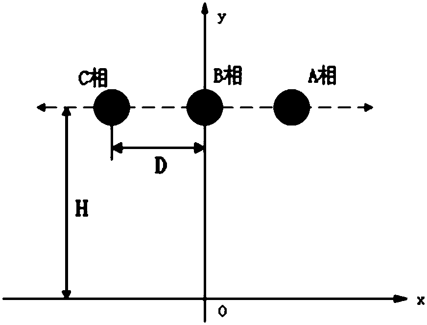
Figure 1 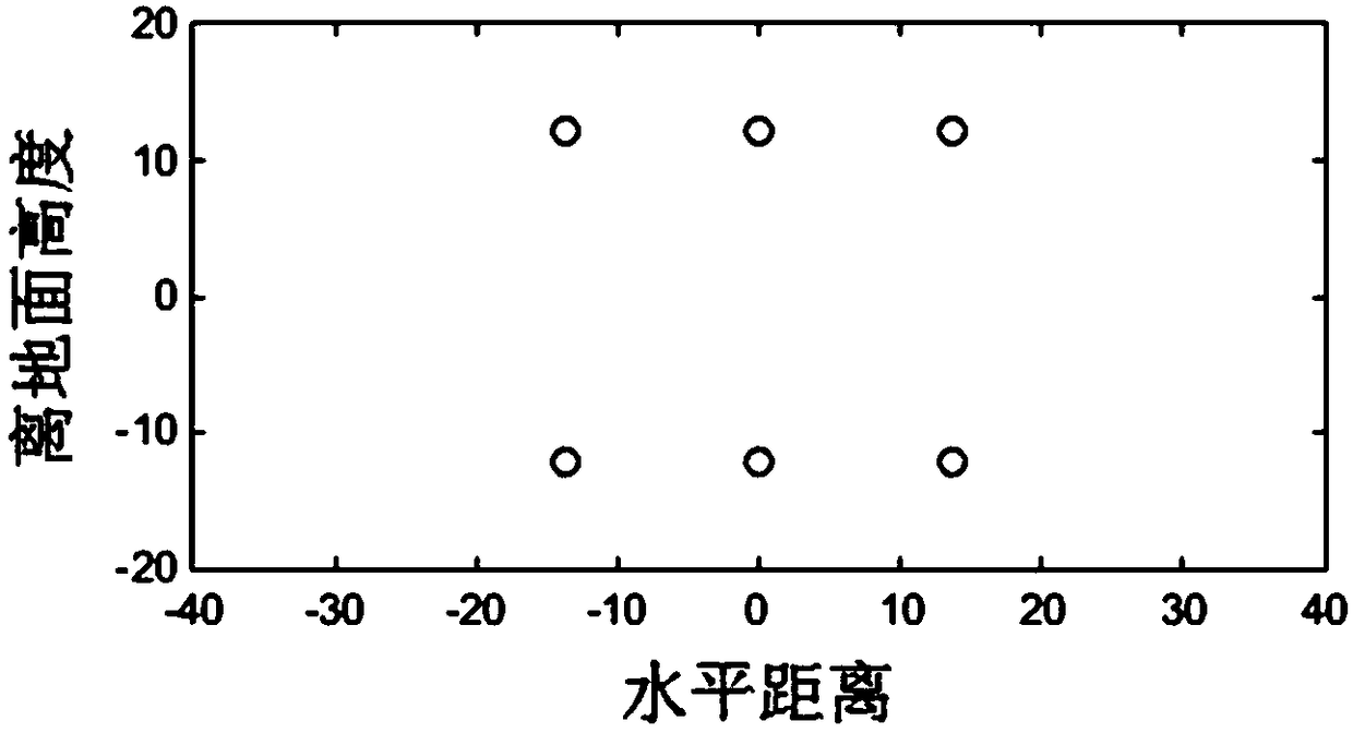
Figure 2 
Figure 3
Abstract
Description
technical field
[0001] The invention relates to the technical field of autonomous navigation of unmanned aerial vehicles, in particular to an autonomous navigation system and method for unmanned aerial vehicles based on equipotential surfaces of electric fields in UHV line areas. Background technique
[0002] The inspection work of the UHV power grid is an important part of the use and maintenance of the UHV power grid project, and it is also a necessary and basic work to ensure the safety of the line. In the long-term operation and maintenance of transmission lines, the State Grid actively applies new technologies to line inspections, among which drone inspections are a technology that has been widely promoted and applied in recent years.
[0003] However, compared with high-voltage and ultra-high-voltage transmission lines, the structure of UHV transmission lines is more complex and the transmission voltage is higher. A strong electromagnetic field is generated around, wh...
Examples
Embodiment
[0045] This embodiment has carried out the field model experiment of the ultra-high voltage transmission line, the ultra-high voltage transmission line in the set model is 500KV, and the approximate relationship between the distance (D) between the transmission lines and the distance (H) from the ground of the transmission line is as follows figure 1 As shown, phase A, phase B, and phase C represent the three transmission lines on the tower respectively. The radius of the four split wires is 0.3m, and the radius of the secondary split wire is 0.0418m. Taking the ground as the zero potential and considering the ground as a good conductor, an analog charge can be set on the mirror position of the wire corresponding to the ground, which equivalently replaces the influence of the induced charge on the performance of the ground.
[0046] Set matching points on the surface of each phase conductor, and solve the following matrix to obtain the simulated charge τ n(m) for:
[0047] ...