Eureka AIR delivers breakthrough ideas for toughest innovation challenges, trusted by R&D personnel around the world.

Fine stablization disturbance decoupling method for composite axis photoelectric tracking system of motion platform

A technology of optoelectronic tracking system and motion platform, which is applied in the direction of control using feedback, etc., can solve the problems of narrow disturbance suppression frequency band, phase advance of low frequency part of disturbance signal, loss of low frequency disturbance information, etc., to achieve simple algorithm and easy engineering implementation. Effect

Pending Publication Date: 2018-08-31
INST OF OPTICS & ELECTRONICS - CHINESE ACAD OF SCI
View PDF0 Cites 11 Cited by
  • Summary
  • Abstract
  • Description
  • Claims
  • Application Information

AI Technical Summary

Problems solved by technology

A commonly used fine-stable disturbance decoupling method is the high-pass filtering method. The advantage of this method is that it is simple, but it will lose the low-frequency disturbance information, and cause the low-frequency part of the remaining disturbance signal to lead in phase after filtering, thus making the secondary Stable and effective disturbance suppression frequency band is very narrow
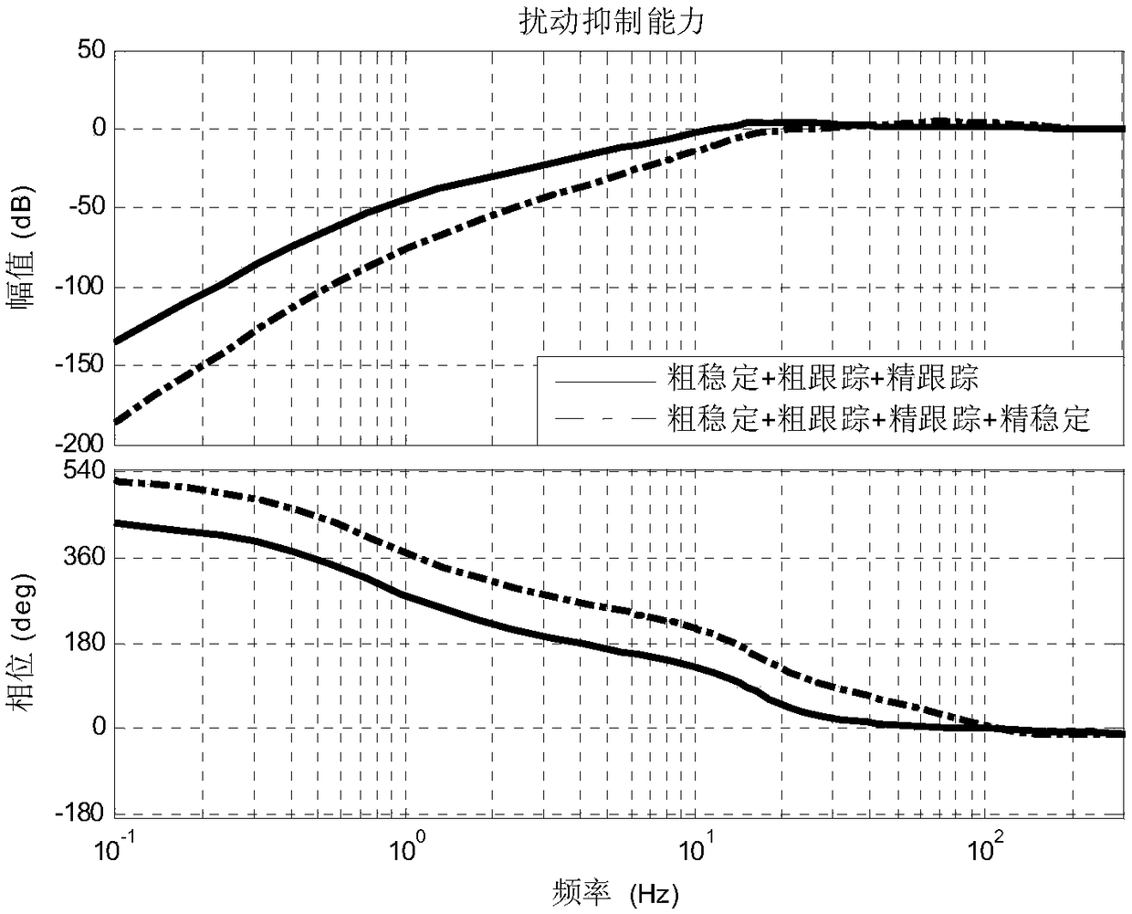
Another method is to directly decouple the angular velocity signal based on the internal model principle, and the obtained signal has filtered out the target information, but this method obtains the rough stability loop of the frame to suppress the remaining disturbance, and does not filter out the coarse Tracking loop disturbance suppression ability, if the disturbance obtained by this method is directly used for fine stability control, although the disturbance suppression ability of the system in the middle frequency band will be improved, but the disturbance suppression ability of the rough tracking loop will be lost in the low frequency band

Method used


Image

  • Fine stablization disturbance decoupling method for composite axis photoelectric tracking system of motion platform
  • Fine stablization disturbance decoupling method for composite axis photoelectric tracking system of motion platform
  • Fine stablization disturbance decoupling method for composite axis photoelectric tracking system of motion platform

Examples


Embodiment Construction

[0016] The present invention will be described below in conjunction with the accompanying drawings and specific embodiments, and those skilled in the art can understand the functions and advantages of the present invention according to the content disclosed in this specification.

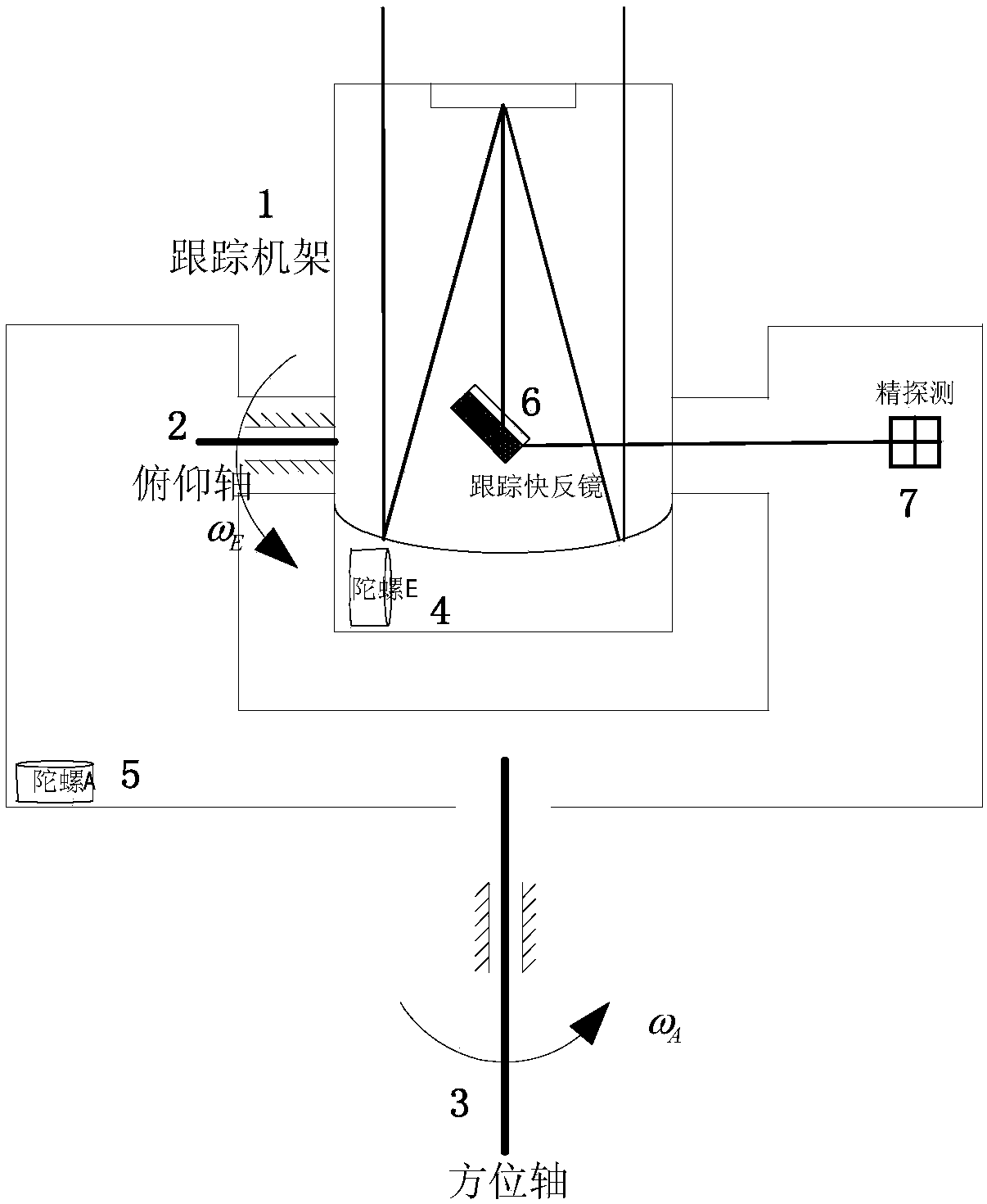
[0017] (1) Angular rate gyros A and E are respectively installed on the azimuth axis and the pitch axis of the tracking frame, and the angular velocity of the azimuth axis and the pitch axis of the sensitive frame is sensitive. Let the rack speed characteristic transfer function be: Design rack speed loop controller C 1 (s) are:

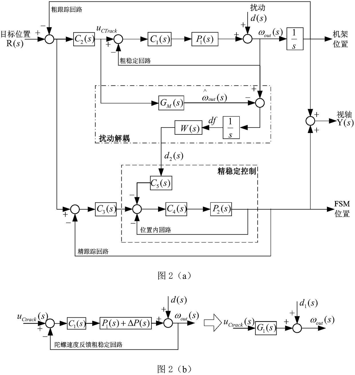
[0018] (2) Establish the frame speed loop closed-loop model G M (s), design G M (s) are: Simultaneously input the target angular velocity to the frame velocity loop and G M (s), the outputs of the two are ω out (s) and is the residual disturbance after active coarse stability loop suppression.

[0019] (3) Design a rough tracking controller C 2 (s), fine tr...


PUM


Abstract

The invention provides a fine stablization disturbance decoupling method for a composite axis photoelectric tracking system of a motion platform, which is mainly used for decoupling the target motionsignal and the disturbance signal in the rough tracking frame gyro information, estimates the residual disturbance after the combined action of the coarse stabilization and coarse tracking of the frame and uses the tracking mirror to suppress the decoupled residual disturbance. A tracking frame contains a coarse tracking loop and a coarse stabilization loop, and a coarse stabilization loop model is established as GM(s). The coarse tracking loop control quantity is used as the input of the coarse stabilization loop and its model GM(s), the two outputs are subtracted to obtain the coarse stabilization residual disturbance df(s), and then the df(s) is multiplied by a coarse tracking error transfer function W(s) to obtain the residual disturbance d2(s) after rough stabilization and coarse tracking. The decoupled d2(s) is subjected to feedforward control to the tracking mirror to constitute a fine stabilization, thereby improving the system disturbance suppression capability. The method does not need to add additional sensors, is simple and effective, and is easy to implement in engineering.

Description

technical field [0001] The invention belongs to the field of inertial stability control, and in particular relates to a precise stability disturbance decoupling method for a compound axis photoelectric tracking system of a motion platform. Background technique [0002] The boresight of the photoelectric system on the moving carrier will be affected by the disturbance of the carrier. Therefore, a stability control subsystem must be established to isolate the disturbance of the carrier so that the boresight of the system will not be affected by the disturbance. The commonly used inertial stability control scheme is to install an inertial rate sensor on the tracking frame, and the frame uses an inertial rate sensor to feedback a closed loop. However, due to the large inertia of the frame, the bandwidth of the frame speed stabilization loop is low, and the disturbance suppression capability is limited; and the high-precision inertial sensor is large in size, heavy in weight, and...

Claims


Application Information

Patent Timeline
Patent Type & Authority Applications(China)
IPC IPC(8): G05D3/12
CPCG05D3/12
Inventor 夏运霞包启亮刘子栋王强蒋晶刘翔
Owner INST OF OPTICS & ELECTRONICS - CHINESE ACAD OF SCI
Why Eureka
Eureka Blog
Learn More