A full-band disturbance decoupling method for photoelectric tracking system of motion platform

A photoelectric tracking system and motion platform technology, applied in the direction of using feedback control and target-seeking control, can solve the problems of difficult to achieve broadband disturbance decoupling, loss of disturbance information, low movement frequency, etc., and achieve easy engineering implementation and algorithmic Simple, stable and reliable results

Active Publication Date: 2021-08-13
INST OF OPTICS & ELECTRONICS - CHINESE ACAD OF SCI
View PDF4 Cites 0 Cited by
  • Summary
  • Abstract
  • Description
  • Claims
  • Application Information

AI Technical Summary

Problems solved by technology

Generally, the moving frequency of the target is low. A commonly used disturbance decoupling method is the high-pass filtering method. The advantage of this method is that it is simple, but it will lose the disturbance information of the low frequency part.
In addition, the use of disturbance observations for disturbance observation depends on the accuracy of the controlled object model. The higher the frequency, the less accurate the model is, and it is difficult to achieve broadband disturbance decoupling.

Method used


Image

  • A full-band disturbance decoupling method for photoelectric tracking system of motion platform
  • A full-band disturbance decoupling method for photoelectric tracking system of motion platform
  • A full-band disturbance decoupling method for photoelectric tracking system of motion platform

Examples


Embodiment Construction

[0017] The present invention will be described below in conjunction with the accompanying drawings and specific embodiments, and those skilled in the art can understand the functions and advantages of the present invention according to the content disclosed in this specification.

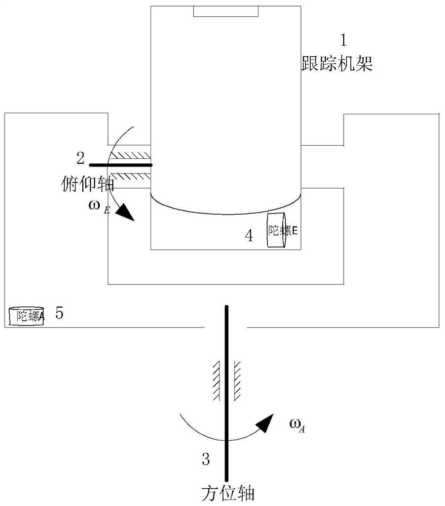
[0018] figure 1 It is a structural schematic diagram of the photoelectric tracking system of the motion platform of the present invention, including a tracking frame 1, a pitch axis 2, an azimuth axis 3, an angular rate gyro E 4, and an angular rate gyro A 5. The angular rate gyro A is installed on the azimuth axis of the tracking frame, and is used for sensing the angular velocity of the azimuth axis in the inertial space, and the angular rate gyro E is installed on the pitch axis, and is used for sensing the angular velocity of the pitch axis in the inertial space.

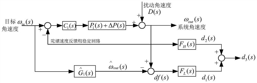
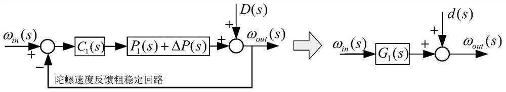
[0019] figure 2 In order to adopt the present invention to carry out disturbance decoupling control structure, image 3 for fig...


PUM


Abstract

The invention provides a full-frequency disturbance decoupling method for a motion platform photoelectric tracking system, which is mainly used for decoupling target motion information and disturbance information in tracking frame gyro signals, and estimating the remaining full-frequency disturbance information after rough stabilization. Angular rate gyros A and E are respectively installed on the azimuth axis and pitch axis of the tracking frame, and the frame velocity loop adopts the gyro feedback closed loop to form a rough stability, and the model of the whole coarse stability loop is recorded as the target angular velocity as the frame rough stability loop The input and the input of its model, the difference between the output of the two is multiplied by the low-pass filter to obtain the disturbed low-frequency part d 1 (s); Multiply the gyro measurement signal by a high-pass filter to obtain the disturbance high-frequency part d 2 (s); will d 1 (s) and d 2 The addition of (s) results in the full-band disturbance after rough stabilization suppression and does not contain target motion information. The invention does not need to add additional sensors, is simple and effective, and is easy to realize engineering.

Description

technical field [0001] The invention belongs to the field of inertial stability control, and in particular relates to a full-frequency disturbance decoupling method for a motion platform photoelectric tracking system. Background technique [0002] The boresight of the photoelectric system on the moving carrier will be affected by the disturbance of the carrier. Therefore, a stability control subsystem must be established to isolate the disturbance of the carrier so that the boresight of the system will not be affected by the disturbance. The commonly used inertial stability control scheme is to install an inertial rate sensor on the tracking frame, and the frame uses an inertial rate sensor to feedback a closed loop. However, due to the large inertia of the frame, the bandwidth of the frame speed stabilization loop is low, and the disturbance suppression capability is limited; and the high-precision inertial sensor is large in size, heavy in weight, and high in cost, which i...

Claims


Application Information

Patent Timeline
Patent Type & Authority Patents(China)
IPC IPC(8): G05D1/12G05D3/12
CPCG05D1/12G05D3/12
Inventor 夏运霞包启亮蒋晶刘子栋唐涛刘翔吴琼王旭
Owner INST OF OPTICS & ELECTRONICS - CHINESE ACAD OF SCI
Why Eureka
Try Eureka