
Power conversion circuit for LED driving

A technology of LED driving and power conversion, applied in electric light sources, adjusting electric variables, electroluminescent light sources, etc., can solve the problems of difficult to guarantee reliability, complicated circuit structure, complicated control methods, etc., and achieve simple structure and wide applicable topology. , the effect of low cost

Inactive Publication Date: 2018-08-31
FOSHAN CHANGJUN TECH CO LTD
View PDF2 Cites 0 Cited by
  • Summary
  • Abstract
  • Description
  • Claims
  • Application Information

AI Technical Summary

Problems solved by technology

[0002] At present, there are many kinds of power conversion circuits used for LED driving. Although various power conversion circuits in the prior art have certain current limiting capabilities and voltage stabilization functions, their control methods are complicated and their reliability is difficult to guarantee. And the circuit structure is complex and the cost is high

Method used


Image

  • Power conversion circuit for LED driving

Examples


Embodiment Construction

[0011] In order to make the objectives, technical solutions, and advantages of the present invention clearer, the following further describes the present invention in detail with reference to the accompanying drawings and embodiments; it should be understood that the specific embodiments described here are only used to explain the present invention and are not used To limit the present invention.

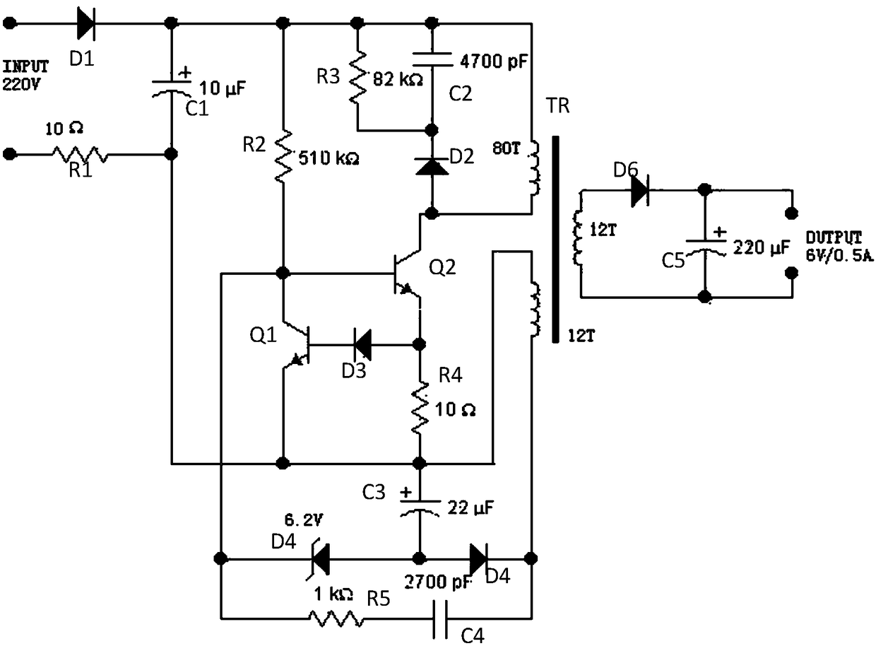
[0012] Reference attached figure 1 , Is a power conversion circuit of the present invention.

[0013] In this embodiment, the input power circuit is 220V AC input, one end is connected to the anode of the second tube D1, the cathode of diode D1 is connected to one end of capacitor C1, resistor R2, resistor R3, capacitor C2, and one end of primary winding L1. The other end of C1 is connected to one end of resistor R1, the emitter of transistor Q1, one end of resistor R4, one end of capacitor C3 and one end of sampling winding L2. The other end of resistor R1 is connected to the other end...


PUM


Abstract

The invention discloses a power conversion circuit for LED driving. The power conversion circuit comprises an AC power supply, a first switch tube and a second switch tube, wherein one end of the AC power supply is connected with a positive electrode of a first diode, and a negative electrode of the first diode is connected with one end of the first capacitor, a second resistor, a third resistor,a second capacitor and one end of a primary winding. In the power conversion circuit, a few components are used, the power conversion circuit is simple in structure and low in cost, stable-voltage output can be achieved, a current of a switch is limited, and the power conversion circuit is prevented from being burnt due to excessive large current and is suitable for promotion.

Description

Technical field [0001] The present invention relates to a power conversion circuit, in particular to a power conversion circuit for LED driving. Background technique [0002] At present, there are various power conversion circuits used for LED driving. Although various power conversion circuits in the prior art have certain current limiting capabilities and voltage stabilization functions, their control methods are complicated and reliability is difficult to guarantee. In addition, the circuit structure is complicated and the cost is relatively high. Therefore, it is very practical to introduce a simple and practical power conversion circuit with current limiting capability and voltage stabilization function to solve this problem. Summary of the invention [0003] The technical problem to be solved by the present invention is to overcome the shortcomings in the prior art and provide a power converter circuit with simple circuit structure and high reliability. It can not only real...

Claims


Application Information

Patent Timeline
Patent Type & Authority Applications(China)
IPC IPC(8): H02M3/335H02M1/32H05B33/08H05B44/00
CPCH02M1/32H02M3/33569H05B45/37
Inventor 刘灿霞
Owner FOSHAN CHANGJUN TECH CO LTD
Learn More