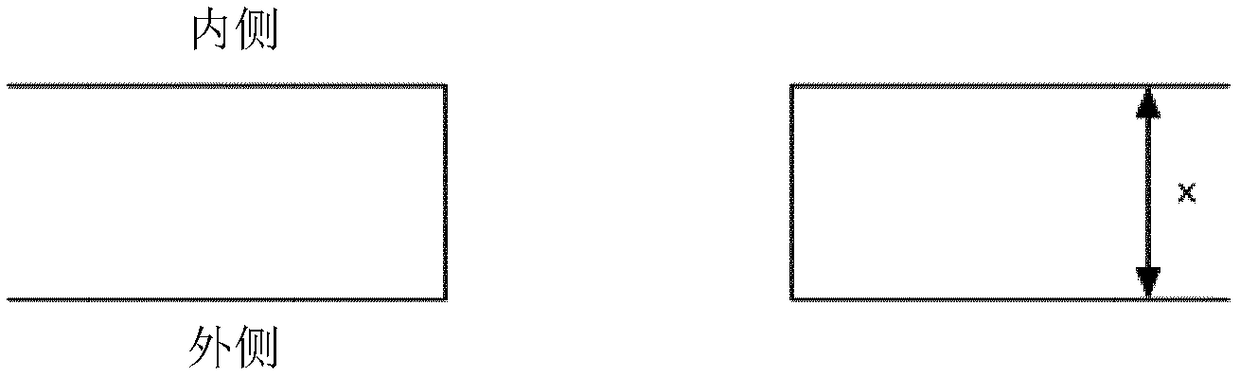
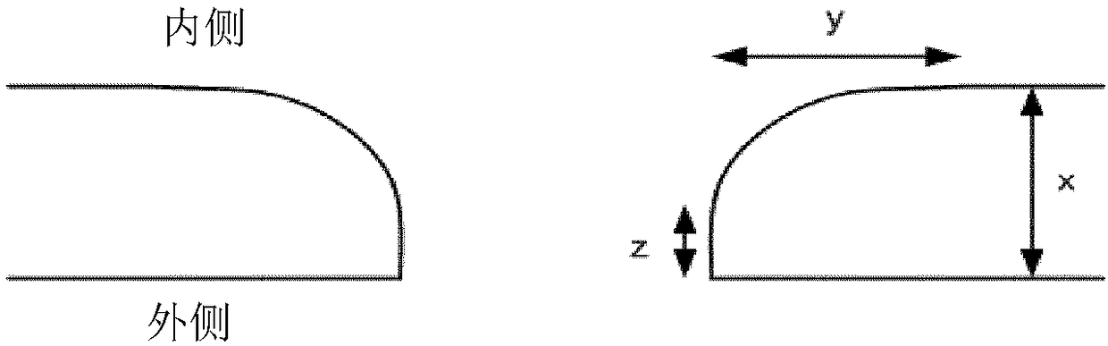
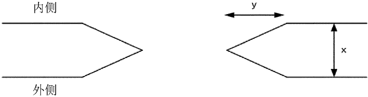
[0045] The packaging material according to the present invention includes a core material layer, an outer layer and an inner layer, wherein the outer layer and the inner layer are applied to opposite sides of the core material layer. The outer layer applied on one side of the core material layer is adapted to provide the outer surface of the package to be produced, the outer surface and the outer layer facing the surrounding environment of the package. The inner layer is applied to the other side of the core material layer and is adapted to provide the inner surface of the package to be produced, the inner surface of which is in contact with the material contained in the package.
[0046] The core material may be a sheet, preferably made of plastic, paper, cardboard or cardboard.
[0047] The outer layer may include at least one layer of polymer material, which is applied to the core material layer. In addition, one of the layers constituting the outer layer may be a decorative layer constituting the outer surface of the package to be formed.
[0048] The printing layer may be included on the core material layer, adjacent to the outer layer.
[0049] The inner layer may include at least one layer of polymer material.
[0050] There may be a protective layer between the core material layer and the inner layer. The protective layer may be a foil, such as a metal foil, preferably an aluminum foil. The protective layer prevents oxygen and light to maintain the nutritional value and flavor of the food in the package at ambient temperature.
[0051] In addition, a laminate layer may exist between the protective layer and the core material layer. The laminate layer may be at least one layer of polymer material.
[0052] According to one embodiment, the layer of the packaging material that is intended to be used inside the finished package and which is in contact with the material contained in the packaging material, starting from the core material layer, includes a laminated layer, a protective layer, and a sealing layer. The laminate layer enables the core material to adhere to any protective layer applied. The sealing layer enables the package to be sealed.
[0053] The polymer layer of the packaging material can be any type of polymer material, preferably a plastic material, such as polyethylene.
[0054] In order to provide a cap or a closure, the core material layer is provided with holes, wherein the holes on the core material layer and its surroundings are preferably treated so that the cross section of the core material layer surrounding the holes presents an inclined structure. As the thickness of the core material gradually increases from the edge of the hole toward the surrounding environment until the full thickness of the core material is reached, a tilt is obtained. On one or both sides of the core material, the core material thickness can be affected, that is, it is reduced relative to the full thickness of the core material. The overall thickness of the core material may gradually decrease toward the punching, for example, in a linear or non-linear manner. The non-linear reduction in thickness can be exponentially reduced. in figure 1 In, the conventional orthogonal punching in the core material layer is shown. The thickness of the core layer is disclosed as x. in Figure 2-4 In, a core material having a region where the thickness of the core layer decreases in a linear and non-linear manner is disclosed. The full thickness of the core layer is figure 1 It is represented by x. The decreasing core thickness is shown as the radial distance y from the edge of the hole. Any remaining core thickness in an orthogonal manner at the edge of the hole is shown as z.
[0055] According to an embodiment, the variation of the thickness of the core material at the inclined region may be 30-95% of the thickness of the core material. In addition, the thickness of the core material at the edge of the hole can be reduced by at least 30%, preferably at least 50%, compared to the full thickness of the core material. Viewed on the z-axis defined as orthogonal to the plane of the core layer, the thickness of the core material at the hole is reduced by at least 30%.
[0056] According to one embodiment, due to the reduced thickness of the core material, the degree of inclination from the edge of the hole in the radial direction of the hole is at least 1 μm, at least 2.5 μm, at least 5 μm, at least 10 μm, at least 50 μm, at least 100 μm, or at least 200 μm from the hole. The extension area can be up to about 2 mm, for example up to about 1 mm, up to about 800 μm, up to 600 μm, up to 400 μm, up to 200 μm, or up to 100 μm. The upper limit and lower limit can be combined into a reasonable range. Viewed from the plane formed along the x-axis and y-axis, there is an angled area of at least 1 μm around the hole where there is a decrease in the thickness of the core material. in Figure 2-4 In and 11, the area with the inclined structure is shown as y.
[0057] According to an embodiment, the radially extending area with the reduced thickness of the core material is positioned on at least one side of the core material layer, preferably on the side of the core material layer intended to be the inside of the package. Alternatively, radially extending regions with reduced core material thickness may be present on both sides of the core material layer, for example image 3 Shown in.
[0058] An inclined or reduced core material thickness can be obtained by compressing and/or cutting the core material layer.
[0059] If the inclination or core material thickness reduction is obtained by compression, this can be done at the same time, before and/or after the hole is made. If the hole is prepared by, for example, an orthogonal punching tool, a compression step may be applied before, during and/or after the punching of the hole. Picture 8 An orthogonal punch tool that punches holes in the core material layer is disclosed. In hole punching, the edge and wall of the hole are orthogonal to each other. By applying pressure to the edge of the hole and its surroundings, the core material layer is compressed. Preferably, the applied compression is greater at the immediate edge of the hole and gradually decreases in a radial direction away from the edge of the hole, for example, in a linear or non-linear manner. Viewing the core layer in cross section, this compression results in a taper around the holes on the side of the core material layer undergoing compression. in Figure 7 In one embodiment shown, compression is applied to the side of the core material layer that is expected to face the inside of the finished package.
[0060] As an alternative or in addition to compression, the hole can be made with an oblique punch tool, resulting in the core layer having an oblique cross section extending outward from the aperture. This is Picture 10 Shown in.
[0061] In one embodiment, punching is performed from one side of the core material layer that is expected to face the inner side of the finished package.
[0062] A punching system with at least two punching tools can be provided. If at least two punching tools are used to punch the holes, the punching tools may have different punching directions to obtain an inclination on both sides of the core material layer. The punching tool may be adapted to punch holes at an oblique angle (less than a right angle) relative to the plane in which the core material layer is located. The two punching tools can be positioned opposite to each other on the same side or opposite sides on the core material layer and the plane it forms. Preferably, the minimum angle between each punching tool and the plane where the core material layer is located is approximately the same for both punching tools. Picture 10 An inclined punch tool for punching holes in a core material layer is disclosed. The two punching tools can be positioned orthogonally with respect to each other. One or more punching tools can be positioned in any direction relative to the machine, but the position in the machine direction is preferably a position transverse to the machine direction, that is, transverse to the transport direction of the machine. The position of the punching tool in the machine direction means that the tool extends and retracts in the same direction as the transport direction of the core material through the packaging material production machine, that is, extends and retracts along the transport axis of the core material in the packaging material production machine. The position in the machine direction provides a gentle thickness variation of the core material layer. This means that the holes are made at different angles. It has been found that providing holes with an angle of 90° or less in the core material layer improves the layer adhesion during the subsequent lamination process. In this case, the punching tool is inclined and not orthogonal to the surface of the core material layer. The hole may be punched out so that the area of the core material layer surrounding the edge of the hole is inclined on both sides of the core material layer. In one embodiment, the hole is preferably made by punching twice at an angle of 90° or less with respect to the surface of the core material layer, wherein the two punch tool parts are related to each other at an angle of 10-178°, for example at 20- The angles of 170°, 40-160° or 50-150° are related to each other. If two oblique punching tools are used, they can be positioned at an angle of at least 90° relative to each other. Therefore, the holes cut in the core layer will affect both sides of the core layer so that its cross-section will show an inclination from both sides. The hole may be cut at an angle of 1-85° with respect to the surface of the core layer, for example at an angle of 5-80°, 10-70°, or 15-65°. According to an embodiment, due to the reduced thickness of the core material, the inclination from the hole edge is set to extend radially from the hole edge at least 1 μm, preferably at least 2.5 μm, preferably at least 5 μm. In this type of hole cutting, the area affected by the inclination, that is, the reduced core material thickness, may preferably be at least 100 μm away from the hole, for example at least 200 μm. The extension area can be up to about 1 mm, for example up to about 800 μm.
[0063] In an embodiment, the side of the core layer with the inclined thickness profile surrounding the hole may be the side on which the subsequent layer is applied first. Using a sloped core material layer thickness profile towards the pre-made hole helps any subsequent layers (eg, laminate layer and protective layer) to be smoothly attached to the edge of the hole. The improved attachment provides greater layer adhesion at the holes and hole edges of the finished packaging material. During and/or after the application of the laminate layer and/or protective layer, the opposite side of the core material layer may be in contact with the nip roller. Figure 5 The contact between the nip roll and the core layer with the applied layer is disclosed. The nip roller can have a larger size, that is, a larger diameter. The combination of inclination and contact with the curved surface of the nip roller will have the effect that the layer applied to the side of the core layer will be able to adhere better at the area of the core material layer that has an oblique thickness profile area To the core layer. As a result, a gentler layer combination is obtained, and the adhesion between these layers around the hole area is improved.
[0064] Stretching of the layers applied to the core material layer can be performed to provide gentle attachment between the layers.
[0065] During the further production of the packaging material, the core material including the laminated layer and the protective layer may be provided with a sealing layer. Preferably, the opposite side of the core material layer is in contact with a small-sized nip roll, that is, the diameter is smaller than the diameter of the roll previously used to apply the laminate layer and the protective layer. Here, the small diameter nip roll stretches the laminate layer and the protective layer, especially the protective layer. During and/or after application of the sealing layer, the opposite side of the core material layer may be in contact with the nip roller. Image 6 The contact between the nip roll and the core layer with the applied layer is disclosed. As a result, a more gradual layer combination is obtained, and the adhesion between these layers around the area of the hole will be maximized.
[0066] The other side of the core layer intended for the outer part of the package to be produced may be coated before or after the application of the layer on the inside of the packaging material. in Figure 7 In, a packaging material is shown with a core layer with applied layers on both sides.
[0067] Picture 9 A conventional packaging material is disclosed, which has holes made orthogonal to the surface of the core layer with a punch. Such packaging materials may exhibit adhesion problems between layers, such as adhesion problems at the intersection between the edge of the hole, the outer layer and the first layer on the opposite side of the core layer, which is undesirable.
[0068] Figure 7 An embodiment is disclosed in which the edge of the hole and the surrounding area have a decreasing core thickness profile, which results in Picture 9 Compared with the embodiment in, the layer adhesion at and around the hole is improved.
[0069] Picture 11 Another embodiment is disclosed in which the edge of the hole and the surrounding area have a decreasing core layer thickness profile on both sides of the core layer, which results in a further improved adhesion between the layer at and around the hole.
[0070] In accordance with the invention Picture 11 In the embodiment, it is shown that the core material layer (for example, cardboard) can be coated with an outer layer, which is shown here as the upper layer on top of the cardboard. On the other side of the core material layer, counting from the core material layer shows: laminated layer, protective layer and sealing layer.
[0071] Packaging materials can be obtained by the process of the present invention. Different types of containers can be obtained from the packaging material according to the present invention. The packaging material or container according to the present invention may be used for food, which may preferably be liquid.