Chiller device

A technology of refrigeration device and control device, which is applied in refrigerators, refrigeration components, measuring devices, etc., to achieve the effect of clear structure and effect, high-precision thermal insulation control

Active Publication Date: 2018-08-31
SHINWA CONTROLS
View PDF14 Cites 2 Cited by
  • Summary
  • Abstract
  • Description
  • Claims
  • Application Information

AI Technical Summary

Problems solved by technology

[0002] Among such refrigeration devices in the prior art, as a single type proposed by the present applicant, a "refrigeration device" having improved the following structure and function (see Patent Document 1): When the temperature difference between the temperature of the working object is close (for example, 5°C to 10°C) and the heat preservation setting is small, especially in the state where the refrigerant temperature difference between the refrigerant inlet side and the refrigerant discharge side of the evaporator in the refrigeration cycle is almost non-existent , although there is no need for refrigerant to flow through the evaporator, the electric compressor will continue to work

Method used


Image

  • Chiller device
  • Chiller device
  • Chiller device

Examples


Embodiment

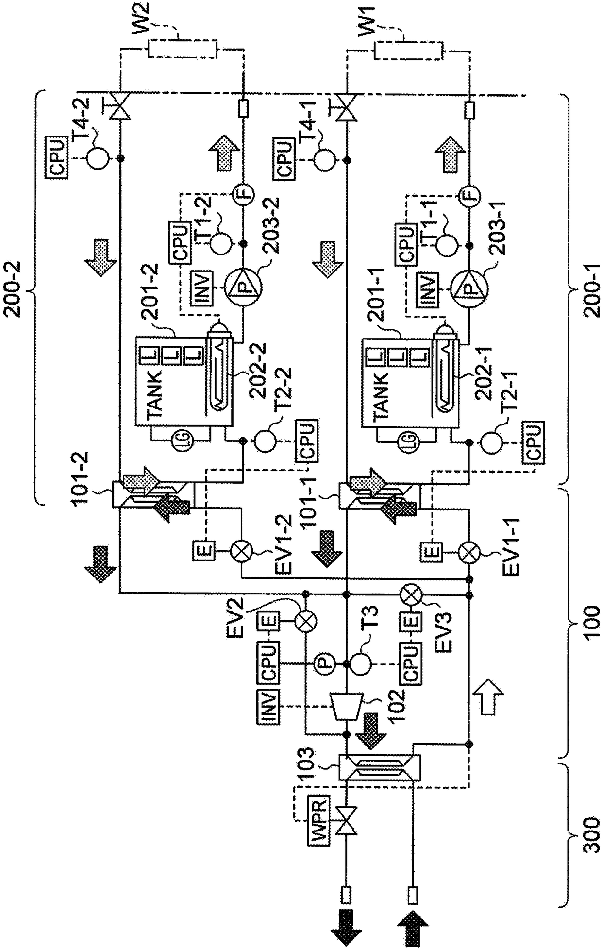
[0021] figure 1 It shows the basic structure of the refrigeration device according to the embodiment of the present invention and is used to connect with the work objects W1 and W2 in the refrigerant cycles 200-1 and 200-2 and to perform the condenser 103 in the refrigeration cycle 100. The overall schematic diagram of the cooling circuit 300 for cooling.

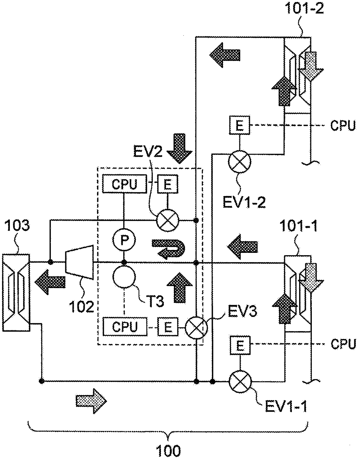
[0022] Reference figure 1 The refrigeration device has a basic structure: a refrigeration cycle 100, which circulates a cooling refrigerant (R410, etc.); a first refrigerant cycle 200-1, which circulates a liquid refrigerant for heating, and shares the refrigeration cycle 100 has a first evaporator (heat exchanger) 101-1; a second refrigerant cycle 200-2, which allows the refrigerant to pass through a bypass flow path that is bypassed through a pipe at a predetermined position of the refrigeration cycle 100 It circulates in a second evaporator (heat exchanger) 101-2 that is different from the first evaporator 101-1, and circul...


PUM


Abstract

Provided is a chiller device having a function of enabling accurate and simultaneous heat-insulation control on workpieces having heat-insulation range conditions which are different from each other,by an inexpensive structure but without impairing the cooling performance and without applying overload to a compressor. In this device, when a coolant having a temperature reduced by cooling is flowed in to an evaporator (101-2) in a coolant cycle (200-2), to which a workpiece (W2) is connected, through bypass flow paths formed by first to fourth flow paths connected to a cooling cycle (100) using an evaporator (101-1) in a coolant cycle (200-1) in a shared manner, to which a workpiece (W1) is connected, the opening degree, at a valve (EV2), of the second flow path is caused to be constant bya pulse signal, which a CPU has generated on the basis of a result obtained by performing PID calculation based on a coolant pressure sensed by a sensor (P) in the cycle (100) and based on a coolanttemperature sensed by a sensor (T3) in the cycle (100), and the opening degree, at a valve (EV3), of the third flow path is variably set and the operation frequency at an electric compressor (102) isvariably controlled within a predetermined range by drive-control signal output such that the flow rate of the coolant circulating, from the valve (EV2), to the compressor (102) via a part of the first flow path converges on a target value.

Description

Technical field [0001] The present invention relates to a refrigerating device, which is used to use various user equipment as the object of heat preservation as the work object, and is selectively set by the user in a predetermined temperature range (for example, -10°C to 100°C) In particular, it relates to a refrigeration device that has the following function: according to the temperature difference between the set temperature and the temperature of the working object, the control device is used to rotate the electric compressor of the refrigeration cycle for cooling. The number and the heating temperature of the heating device included in the heating refrigerant cycle are controlled. Background technique [0002] Among such refrigeration devices in the prior art, as a single type proposed by the applicant, there is a "refrigeration device" that has improved the following structure and functions (see Patent Document 1): When the temperature difference between the working targ...

Claims


Application Information

Patent Timeline
Patent Type & Authority Applications(China)
IPC IPC(8): F25B5/02F24F5/00F24F11/89F25B1/00F25B5/00
CPCF25B1/00F25B5/00F25B5/02F24F5/00F24F11/89
Inventor 上田祯一郎石松卓也细井史幸
Owner SHINWA CONTROLS
Why Eureka
Try Eureka