
Continuous reservoir level monitoring

A reservoir and liquid level technology, applied in the field of lubrication systems, can solve problems such as inability to provide accurate lubricant liquid level readings

Inactive Publication Date: 2018-08-31
GRACO INC
View PDF12 Cites 3 Cited by
  • Summary
  • Abstract
  • Description
  • Claims
  • Application Information

AI Technical Summary

Problems solved by technology

Therefore, physical means of tracking the surface level of grease may not provide accurate lubricant level readings due to surface deformation as the grease level is depleted

Method used


Image

  • Continuous reservoir level monitoring
  • Continuous reservoir level monitoring
  • Continuous reservoir level monitoring

Examples


Embodiment Construction

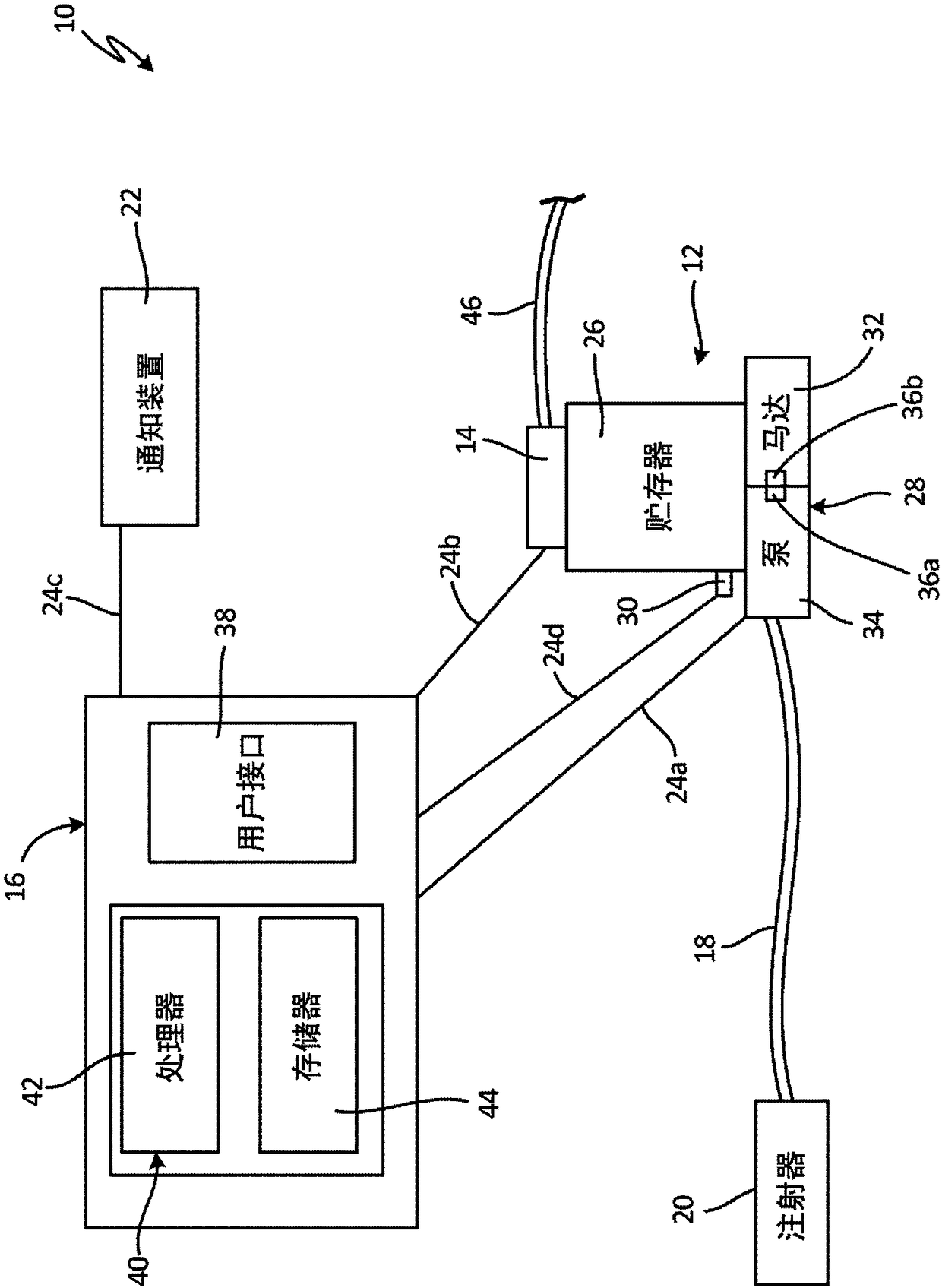
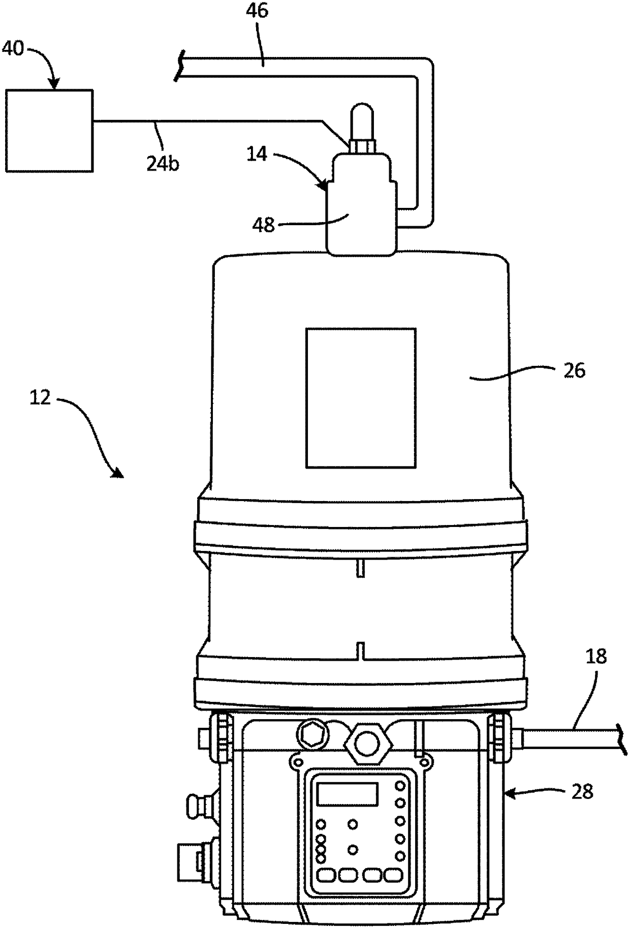
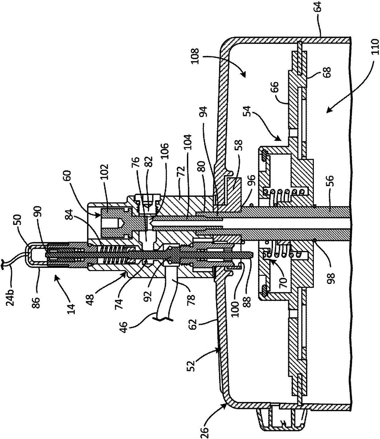
[0014] figure 1 is a schematic block diagram of the lubrication system 10 . Lubrication system 10 includes reservoir assembly 12, high level sensor 14, control system 16, supply line 18, injector 20, notification device 22, and communication links 24a-24d. The reservoir assembly 12 includes a lubricant reservoir 26 and a pump assembly 28 . Lubricant reservoir 26 includes a low level sensor 30 and pump assembly 28 includes a motor 32 and a pump 34 . The pump 34 includes a displacement sensor 36a, and the motor 32 includes a displacement sensor 36b. The control system 16 includes a user interface 38 and a lubricant level estimator 40 . Lubricant level estimator 40 includes processor 42 and memory 44 .

[0015] Lubrication system 10 is a specialized lubrication system for lubricating machinery that includes components such as pumps, pistons, seals, bearings and / or shafts. Lubricant reservoir 26 is mounted on pump assembly 28 . Lubricant reservoir 26 stores lubricant prior t...


PUM


Abstract

The lubricant level within a reservoir is difficult to monitor, leading to the reservoir being refilled more often than necessary to ensure that the reservoir always contains lubricant. A lubricant level sensing system is connected to and monitors various aspects of the pump assembly that draws lubricant from the reservoir. The pump assembly displaces a known volume of lubricant with each pump stroke. A lubricant-level estimator calculates an estimated lubricant level remaining in the reservoir based on a stroke-count value as sensed from the pump assembly and on a reference value stored in amemory. The estimated lubricant level provides the lubricant remaining and the rate of usage such that maintenance can be scheduled ahead of time to prevent the reservoir from running dry.

Description

[0001] Cross reference to related applications [0002] This application claims priority to US Provisional Application No. 62 / 279,884, entitled "Continuous Reservoir Grease Level Monitoring," filed January 18, 2016, the disclosure of which is incorporated herein by reference in its entirety. technical field [0003] The present disclosure generally relates to lubrication systems. More specifically, the present disclosure relates to systems and methods for sensing a lubricant level in a lubricant reservoir. Background technique [0004] Machinery often requires lubrication to function. Seals, pistons, bearings and other components require lubrication with small amounts of grease or oil at too short, frequent intervals to prevent wear, corrosion, over- or under-lubrication. Lubricant is injected through the lubricant injector at specific locations that require lubrication. A local lubricant reservoir stores lubricant until lubricant is applied. Lubricant reservoirs have a ...

Claims


Application Information

Patent Timeline
IPC IPC(8): G01F23/00
CPCF04B39/00F16N29/00F04B49/02F04B49/06F04B53/18F16N7/385F04B2201/0201F04B2201/0209F16N2250/18F01M11/12F04C14/28F04C14/00G01F23/80F04B39/0207F16N29/02
Inventor 布兰登·T·古斯塔夫森苏瑞萨·萨拉胡·尼娅古娜乍德·G·艾格
Owner GRACO INC
Learn More