Plug and play device identification method and electronic device

A plug-and-play technology for electronic equipment, applied in current collectors, electric vehicles, electrical components, etc., can solve the problems of adding USBIC equipment and high cost

Active Publication Date: 2020-12-22
HONOR DEVICE CO LTD
View PDF4 Cites 0 Cited by
  • Summary
  • Abstract
  • Description
  • Claims
  • Application Information

AI Technical Summary

Problems solved by technology

[0007] However, although the connection structure between the above devices can accurately iden

Method used


Image

  • Plug and play device identification method and electronic device
  • Plug and play device identification method and electronic device
  • Plug and play device identification method and electronic device

Examples


Embodiment Construction

[0027] The technical solutions of the present application will be described in further detail below with reference to the drawings and embodiments.

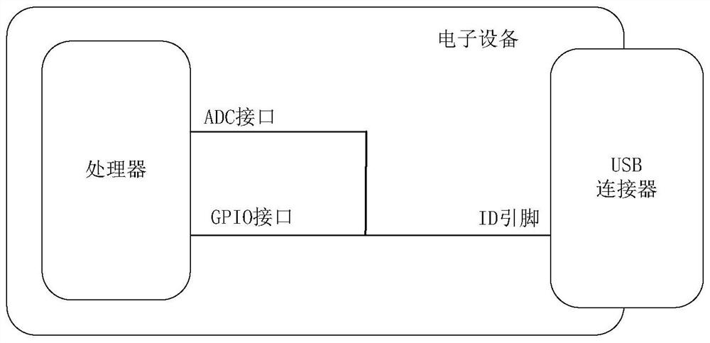
[0028] The identification method of the OTG function of this application can be applied in figure 2 in the electronic device shown. Electronic devices and external devices are connected through USB connectors.

[0029] Wherein, the electronic device may be a digital camera, a video camera, or a mobile phone. The external device can be a printer, a U disk or a memory card, etc.

[0030] like figure 2 As shown, the electronic device may include a processor and a USB connector. The processor may include an analog to digital converter (analog to digital converter, ADC) interface and a GPIO interface.

[0031] Wherein, the ADC interface and the GPIO interface are respectively connected to the ID pin of the USB connector.

[0032] ADC interface for reading the voltage value of the ID pin of the USB connector.

[0033] The GPIO...


PUM


Abstract

The embodiments of the present invention relate to a method for recognizing a plug-and-play device, and an electronic device. In this method, an electronic device determines a device type of an external device according to a working state of a power bus pin of a universal serial bus (USB) connector. When the device type is a charging-type device, the electronic device enters a charging mode. Alternatively, when the device type is a non-charging-type device, the electronic device acquires a first voltage value of an ID pin of the USB connector. If the first voltage value is greater than a first voltage threshold and is less than a second voltage threshold, the electronic device turns off a plug-and-play OTG function, and the first voltage threshold is less than the second voltage threshold. The method improves the accuracy of identifying the electronic device entering an OTG mode without adding a device, reduces costs, and at the same time, avoids the power consumption generated by frequently awakening the electronic device due to voltage fluctuations of a GPIO port in a non-OTG mode, and prevents the OTG mode from being entered by mistake.

Description

[0001] This application claims the priority of the Chinese patent application submitted to the China Patent Office on December 20, 2016, with the application number 201611186660.9, and the title of the invention is "A method and device for realizing OTG function on electronic equipment", the entire content of which is incorporated by reference Incorporated in this application document. It is only for the sake of concise expression, and its entire content will not be repeated in the original text in this application document. technical field [0002] The embodiment of the present application relates to the technical field of electronic device data interface, and in particular to a method for identifying a plug-and-play device and an electronic device. Background technique [0003] The plug-and-play (On The Go, OTG) technology can realize the connection between various electronic devices for data exchange without a host (Host). [0004] An electronic device (such as a mobile ...

Claims


Application Information

Patent Timeline
IPC IPC(8): G06F13/24G06F13/14H02J7/00
CPCG06F13/14G06F13/24H02J7/00Y02D10/00
Inventor 王朝马雷罗伟
Owner HONOR DEVICE CO LTD
Why Eureka
Try Eureka