Scalable electric generator

A technology of generators and generator discs, which is applied in the direction of controlling generators, engines, wind power generation, etc., and can solve problems such as improvement, impractical feasibility, and multi-power consumption

Inactive Publication Date: 2018-08-31
阿泰尔科技有限公司
View PDF6 Cites 3 Cited by
  • Summary
  • Abstract
  • Description
  • Claims
  • Application Information

AI Technical Summary

Problems solved by technology

To overcome this disadvantage, direct drive turbine solutions are typically used in the industry, however for power generation greater than 6-7 MW the size increases even in direct drive turbines and this becomes the limiting factor, and Feasibility of using the method becomes impractical
[0003] Gearboxes increase the overhead power consumption in the generator compared to direct drive turbines, while direct drive turbines must be formatted for maximum power generation, thus greater than 6-7MW due to size and weight constraints unrealistic
[0004] Therefore, the technical problem in the prior art is that the turbines have too much power overhead when generating more than a certain power level (typically 6-7MW)

Method used


Image

  • Scalable electric generator
  • Scalable electric generator
  • Scalable electric generator

Examples


Embodiment Construction

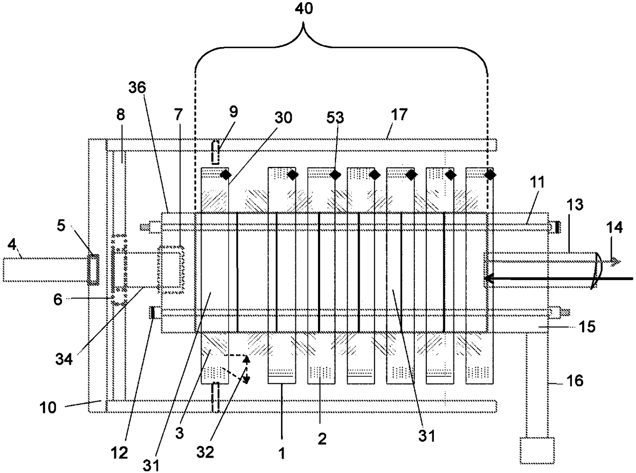
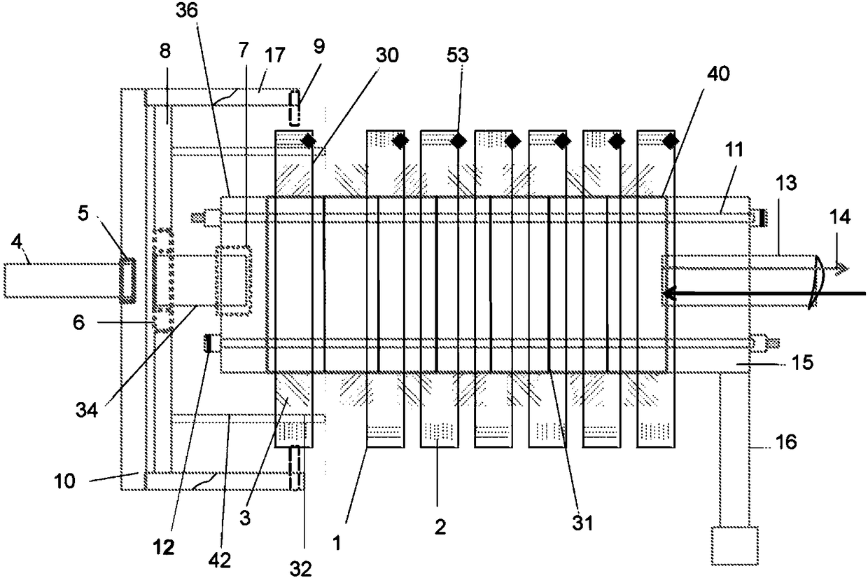
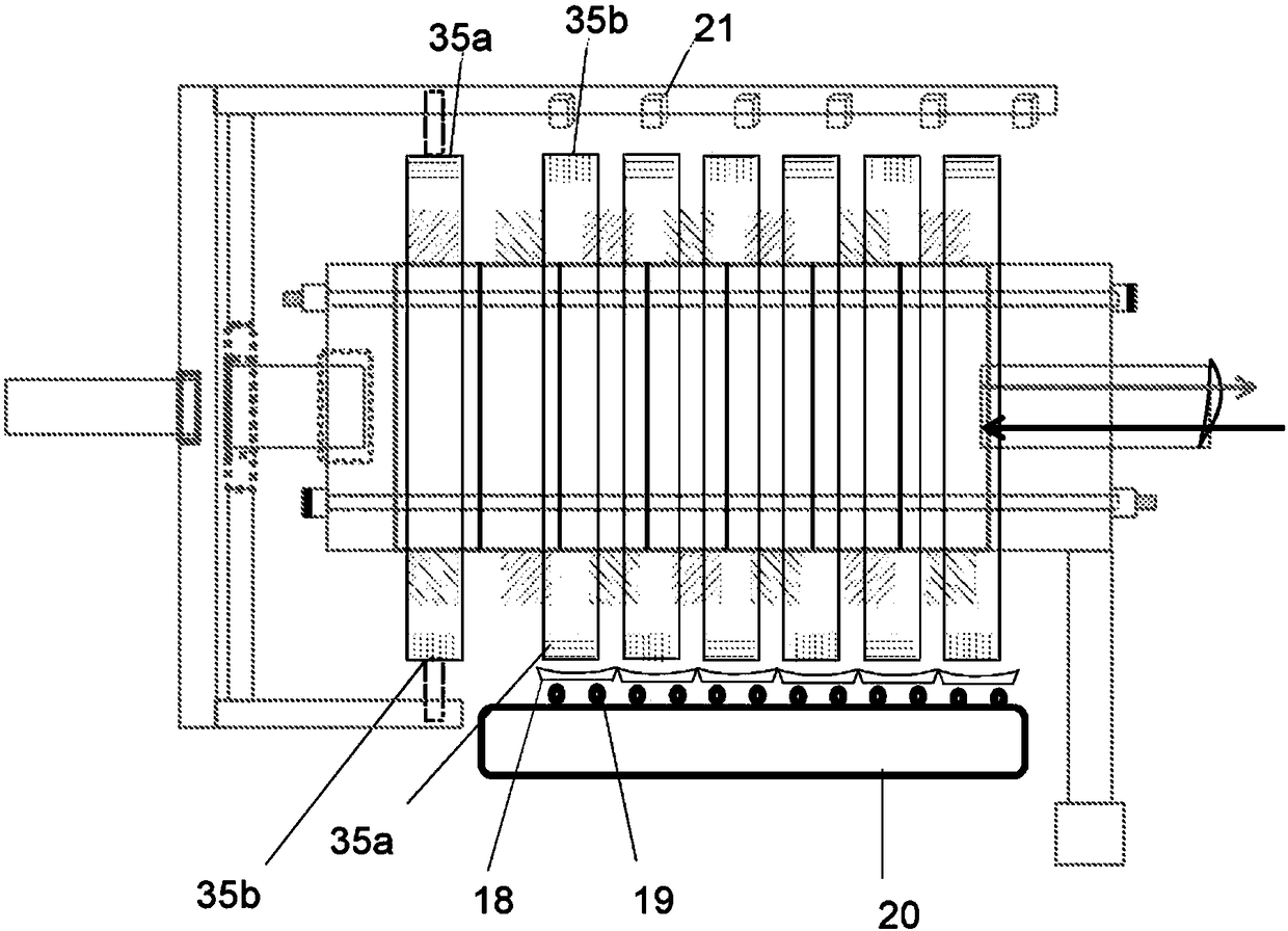
[0033] With reference to accompanying drawing 1-Fig. 10, in Figure 1A and Figure 1B A generator disc assembly 30 according to the present invention is shown in , and is shown in, for example Figure 101a A cross-sectional view of the same generator disc assembly is shown in . In one embodiment, components and structures can be compared with those in Figure 101- Figure 107 The same motor assembly as described in . The rotor ring / frame 1 comprises pairs of magnets 2, wherein the magnets 2 are arranged inwards on the inner surface of the rotor ring 1, and the magnets may be any type of suitable magnets / electromagnets. The rotor ring 1 is arranged on the outside of the armature assembly 3, 31, 104, 106, 105, which includes the stator frame, the stator poles protruding outwards and the corresponding wire windings on the stator poles, so that when current is applied to the windings When the magnetic flux is polarity defined by the winding direction. The inwardly facing magnet...


PUM


Abstract

A method, system and device for an electric generator comprising dynamically selectable number of generator disk assemblies.

Description

technical field [0001] The present invention relates to electrical generators, and more particularly to any type of application in which electrical power can be generated using a direct drive electrical generator. Background technique [0002] In eg the wind turbine industry, it is common practice to custom design gearboxes according to power and speed requirements. The problem for the industry is therefore that in many wind power applications, the extra gearbox increases the weight and number of moving parts in the turbine. To overcome this disadvantage, direct drive turbine solutions are typically used in the industry, however for power generation greater than 6-7 MW the size increases even in direct drive turbines and this becomes the limiting factor, and The feasibility of using this method becomes impractical. [0003] Gearboxes increase the overhead power consumption in the generator compared to direct drive turbines, while direct drive turbines must be formatted for...

Claims


Application Information

Patent Timeline
Patent Type & Authority Applications(China)
IPC IPC(8): H02K21/02H02K16/02H02K21/22H02K23/54
CPCF03D9/25F05B2260/821F05B2270/32H02K7/183H02K16/02H02K21/023H02K21/22H02K2213/09H02K2213/12H02P9/008H02P2101/15Y02E10/72H02K1/18H02K16/04H02K21/125H02K21/145F05B2220/706F05B2260/8211
Inventor 阿帕恩·马西尔拉马尼
Owner 阿泰尔科技有限公司
Why Eureka
Try Eureka