Digital microfluidic chip control platform
A technology of digital microfluidics and manipulation platform, applied in fluid controllers, laboratory utensils, laboratory containers, etc., can solve the problems of heavy work tasks, difficult processing, and high costs, achieve complex biochemical reactions, reduce Replacement cost, the effect of precise control
- Summary
- Abstract
- Description
- Claims
- Application Information
AI Technical Summary
Problems solved by technology
Method used
Image
Examples
Embodiment 1
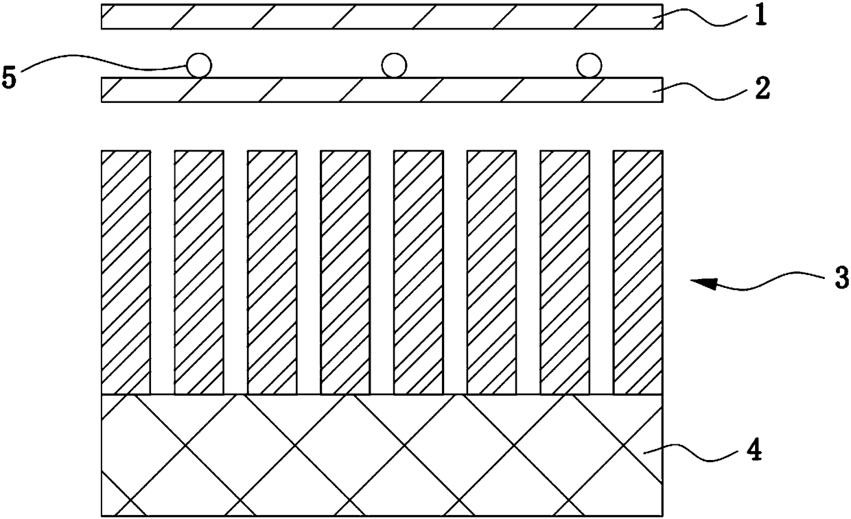
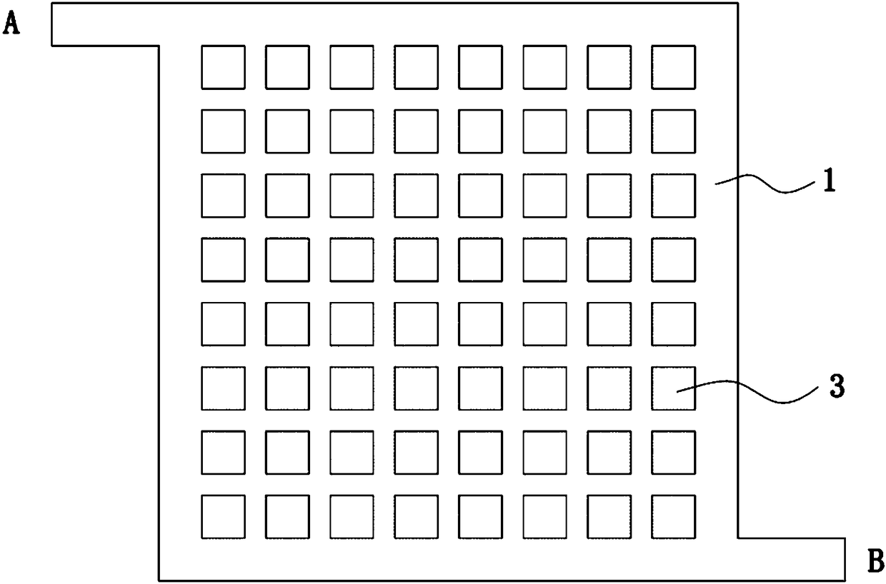
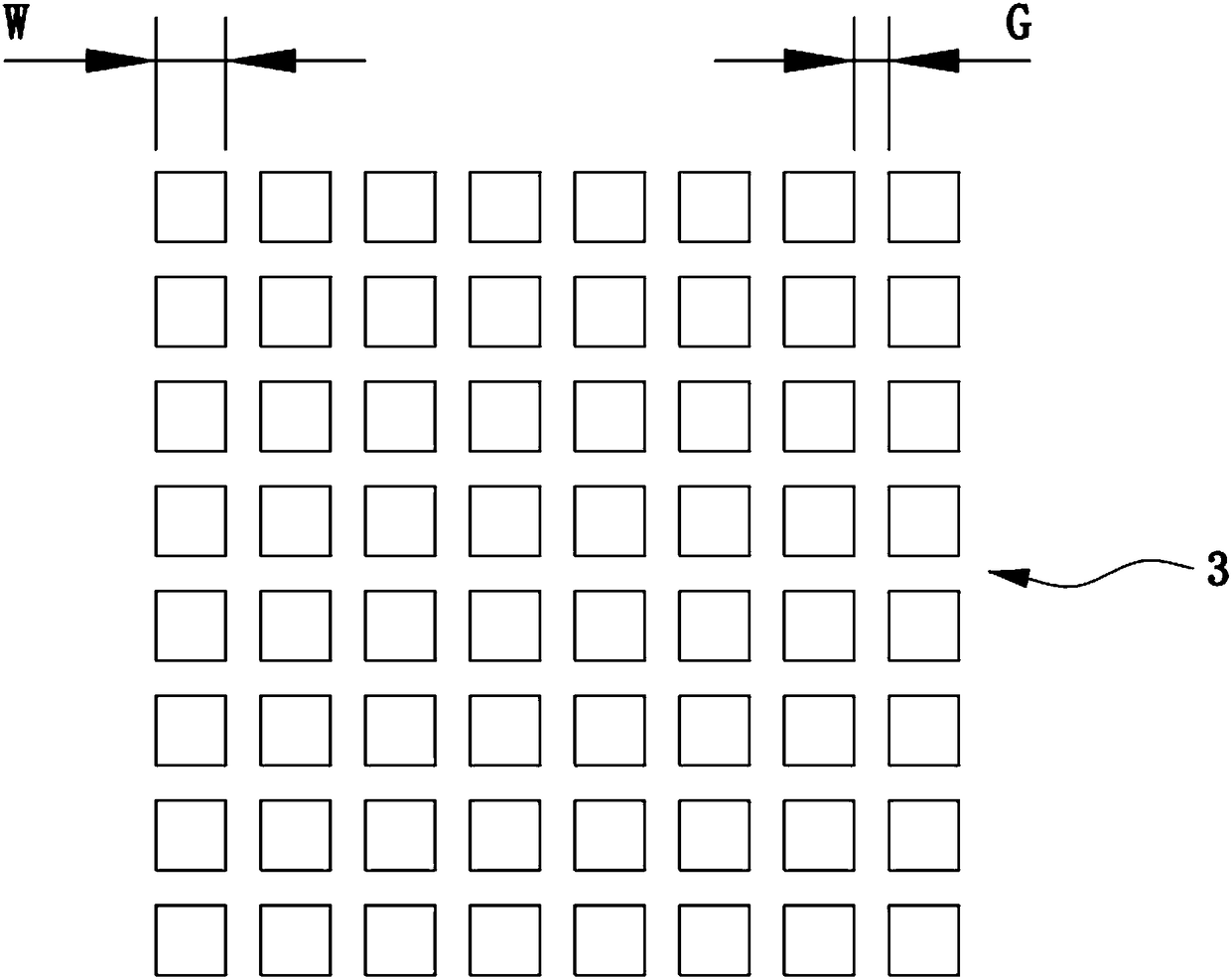
[0042] This embodiment provides a digital microfluidic chip control platform, such as figure 1 As shown, it includes a chip and a magnetic control module, the chip and the magnetic control module are arranged facing each other, the chip is provided with a microchannel for the flow of the micro-droplet 5, the micro-droplet 5 has magnetism, and the magnetic field strength of the magnetic control module is adjustable, so that The movement of the microdroplet 5 can be magnetically controlled.
[0043] According to specific application requirements, magnetic control modules can be installed on the upper and lower sides of the chip to apply a magnetic field to the micro-droplet 5 on both sides of the chip to achieve more precise and complex control of the trajectory and biochemical reactions of the micro-droplet 5 . Preferably, the magnetic control module in this embodiment is arranged directly under the chip.
[0044] By setting the magnetic control module to control the movement...
Embodiment 2
[0065] This embodiment provides a digital microfluidic chip control platform. This embodiment is basically the same as the first embodiment. For the sake of simplicity, only the differences between this embodiment and the first embodiment will be described.
[0066] In this embodiment, the magnet unit 31 of the magnet group 3 is an electromagnetic coil, and the drive unit 41 of the driver 4 is an electrical component. By controlling whether the electrical component is energized or not, the electromagnetic coil is controlled to have magnetism or not, and it can be controlled by controlling the current. The strength realizes the adjustment of the magnetic field strength, thereby changing the magnetic field strength applied to the micro-droplet 5 and controlling the movement of the micro-droplet 5 .
[0067] The manipulation method of this embodiment will be further described below in conjunction with specific examples.
[0068] Figure 9 and Figure 10 It shows a working princ...
Embodiment 3
[0072] This embodiment provides a method for fusion of micro-droplets 5 using Embodiment 1 and Embodiment 2.
[0073] In biochemical reactions, it is often necessary to fuse two reactants and react after applying certain conditions. The digital microfluidic chip control platform provided by the present invention can well realize this function. Fusion, to achieve the purpose of the reaction.
[0074] Specifically, as Figure 14 and Figure 15 as shown, Figure 14 A single magnet unit 31 controls two micro-droplets 5 to move to a specific position. When the two micro-droplets 5 reach this position, they collide and merge, and after merging into a larger micro-droplet 5, as Figure 15 As shown, it is finally located at the center of the magnet unit 31 . As described in Embodiment 1 and Embodiment 2, the micro-droplet 5 can be controlled by a permanent magnet or an electromagnetic coil, or the movement and position of the micro-droplet 5 can be controlled by the magnetic field...
PUM
 Abstract
Description
Claims
Application Information
 - R&D
- Intellectual Property
- Life Sciences
- Materials
- Tech Scout
- Unparalleled Data Quality
- Higher Quality Content
- 60% Fewer Hallucinations
Browse by: Latest US Patents, China's latest patents, Technical Efficacy Thesaurus, Application Domain, Technology Topic, Popular Technical Reports.
© 2025 PatSnap. All rights reserved.Legal|Privacy policy|Modern Slavery Act Transparency Statement|Sitemap|About US| Contact US: help@patsnap.com


