Motor shell paint spaying device with controllable spraying range

A motor casing and range technology, which is applied in the field of motor casing painting devices, can solve the problems of poor spraying effect, uncontrollable spraying range, and low spraying efficiency, so as to achieve the effect of ensuring the painting effect, convenient adjustment and operation, and improving painting efficiency

Inactive Publication Date: 2018-09-04
ZHEJIANG OUDAO AUTOMATION EQUIP CO LTD
View PDF5 Cites 21 Cited by
  • Summary
  • Abstract
  • Description
  • Claims
  • Application Information

AI Technical Summary

Problems solved by technology

[0003] During the manufacturing process of the motor, it is necessary to spray paint on the surface of the motor casing to isolate the surface from the outside atmosphere, avoid the corrosion of sulfide or water vapor in the atmosphere, improve the anti-corrosion performance of the motor casing, and prolong the life of the motor. The service life, most of the existing painting devices have the defects of low spraying efficiency and poor spraying effect, and the spraying range is uncontrollable and cannot be adjusted according to the size of the motor shell, which has certain limitations in use

Method used


Image

  • Motor shell paint spaying device with controllable spraying range
  • Motor shell paint spaying device with controllable spraying range
  • Motor shell paint spaying device with controllable spraying range

Examples


Embodiment Construction

[0022] The technical solutions in the embodiments of the present invention will be clearly and completely described below in conjunction with the accompanying drawings in the embodiments of the present invention. Obviously, the described embodiments are only a part of the embodiments of the present invention, rather than all the embodiments. Based on the embodiments of the present invention, all other embodiments obtained by those of ordinary skill in the art without creative work shall fall within the protection scope of the present invention.

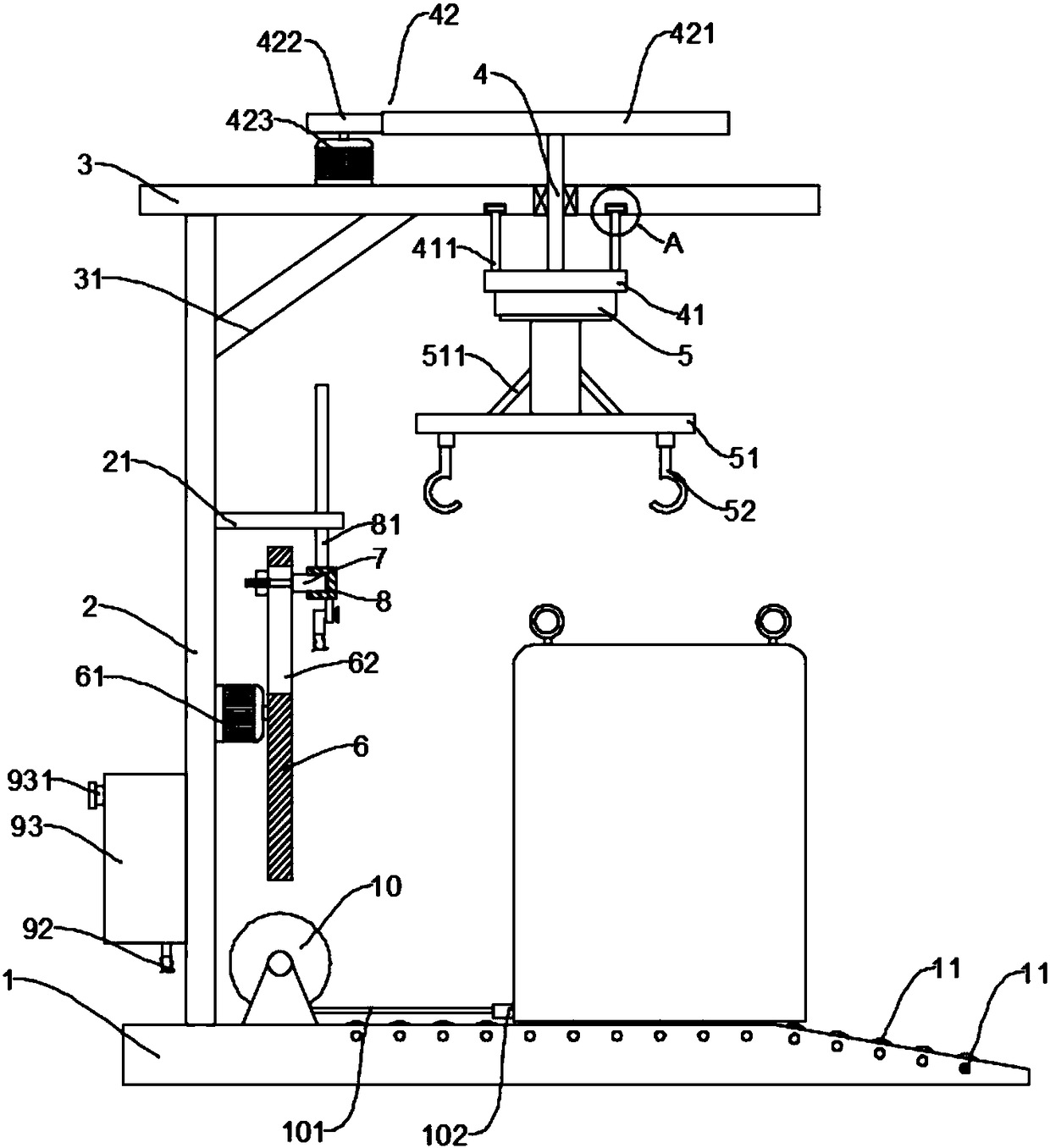
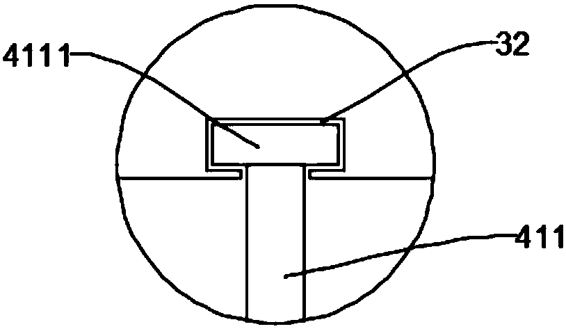
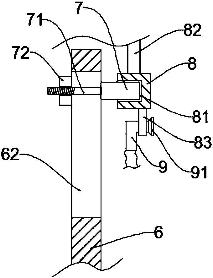
[0023] See Figure 1~5 In the embodiment of the present invention, a spraying device for a motor housing with a controllable spraying range includes a workbench 1, a stand 2, a rotating shaft 4, a lifting device 5, a disc 6, a boss 7, a sliding rod 8 and a spray Tube 9; the stand 2 is fixed on the top left side of the workbench 1, the top of the stand 2 is connected with a top plate 3, and a plurality of diagonal braces are connected bet...


PUM


Abstract

The invention discloses a motor shell paint spraying device with the controllable spraying range. The motor shell paint spraying device comprises a work table, a vertical frame, a rotary shaft, a lifting device, a circular disc, a convex column, a slipping rod and a spraying pipe. The vertical frame is fixed to the left side of the top of the work table, and a top plate is connected to the top ofthe vertical frame. A rotary shaft is arranged on the top plate in a penetrating mode, the upper end of the rotary shaft is provided with a driving mechanism for driving the rotary shaft to rotate, and a base plate is fixed to the bottom of the rotary shaft. The circular disc is arranged on the position below the right side of the vertical frame, the convex column is connected to the right end face of the circular disc in a matched mode, and the slipping rod is longitudinally arranged on the right side of the circular disc. A fixing ring is connected to the center position of the bottom of theslipping rod, and the spraying pipe is arranged in the fixing ring in a penetrating mode. According to the motor shell paint spraying device, efficient paint spaying can be conducted on a motor shell, the paint spraying effect is good, meanwhile the spraying range can further be adjusted correspondingly according to the size of the motor shell, and the applicability of the motor shell paint spraying device is improved.

Description

Technical field [0001] The invention relates to the field of motor processing, in particular to a paint spraying device for a motor housing with a controllable spraying range. Background technique [0002] Motor refers to an electromagnetic device that realizes the conversion or transmission of electric energy according to the law of electromagnetic induction. Its main function is to generate driving torque. As the power source of electrical appliances or various machinery, the generator is represented by the letter G in the circuit. Its main function is to convert mechanical energy into electrical energy. At present, the most commonly used is the use of heat, Hydropower and others push generator rotors to generate electricity. As wind power technology matures, wind power is slowly entering our lives. [0003] In the manufacturing process of the motor, it is necessary to paint the surface of the motor shell to isolate the surface from the outside atmosphere to prevent it from bein...

Claims


Application Information

Patent Timeline
Patent Type & Authority Applications(China)
IPC IPC(8): B05B13/02B05B13/04H02K15/14H02K15/12
CPCB05B13/0228B05B13/0264B05B13/041H02K15/12H02K15/14
Inventor 谢剑
Owner ZHEJIANG OUDAO AUTOMATION EQUIP CO LTD
Why Eureka
Try Eureka