Pipe machining lathe with automatic feeding function

A technology of automatic feeding and pipe fittings, applied in the direction of automatic/semi-automatic lathes, accessories of tool holders, metal processing equipment, etc., can solve the problems of low work efficiency, achieve the effect of preventing offset and convenient disassembly

Active Publication Date: 2018-09-04
青岛铭和锐金属有限公司
View PDF8 Cites 12 Cited by
  • Summary
  • Abstract
  • Description
  • Claims
  • Application Information

AI Technical Summary

Problems solved by technology

[0005] However, before processing this lathe, workers need to manually install the pipe fittings on the workbench. Every time a pipe fitting is processed, it needs to be manually installed once, and the work efficiency is not high.

Method used


Image

  • Pipe machining lathe with automatic feeding function
  • Pipe machining lathe with automatic feeding function
  • Pipe machining lathe with automatic feeding function

Examples


Embodiment Construction

[0037] The present invention will be described in further detail below in conjunction with the accompanying drawings. Wherein the same components are denoted by the same reference numerals. It should be noted that the words "front", "rear", "left", "right", "upper" and "lower" used in the following description refer to the directions in the drawings, and the words "bottom" and "top "Face", "inner" and "outer" refer to directions toward or away from, respectively, the geometric center of a particular component.

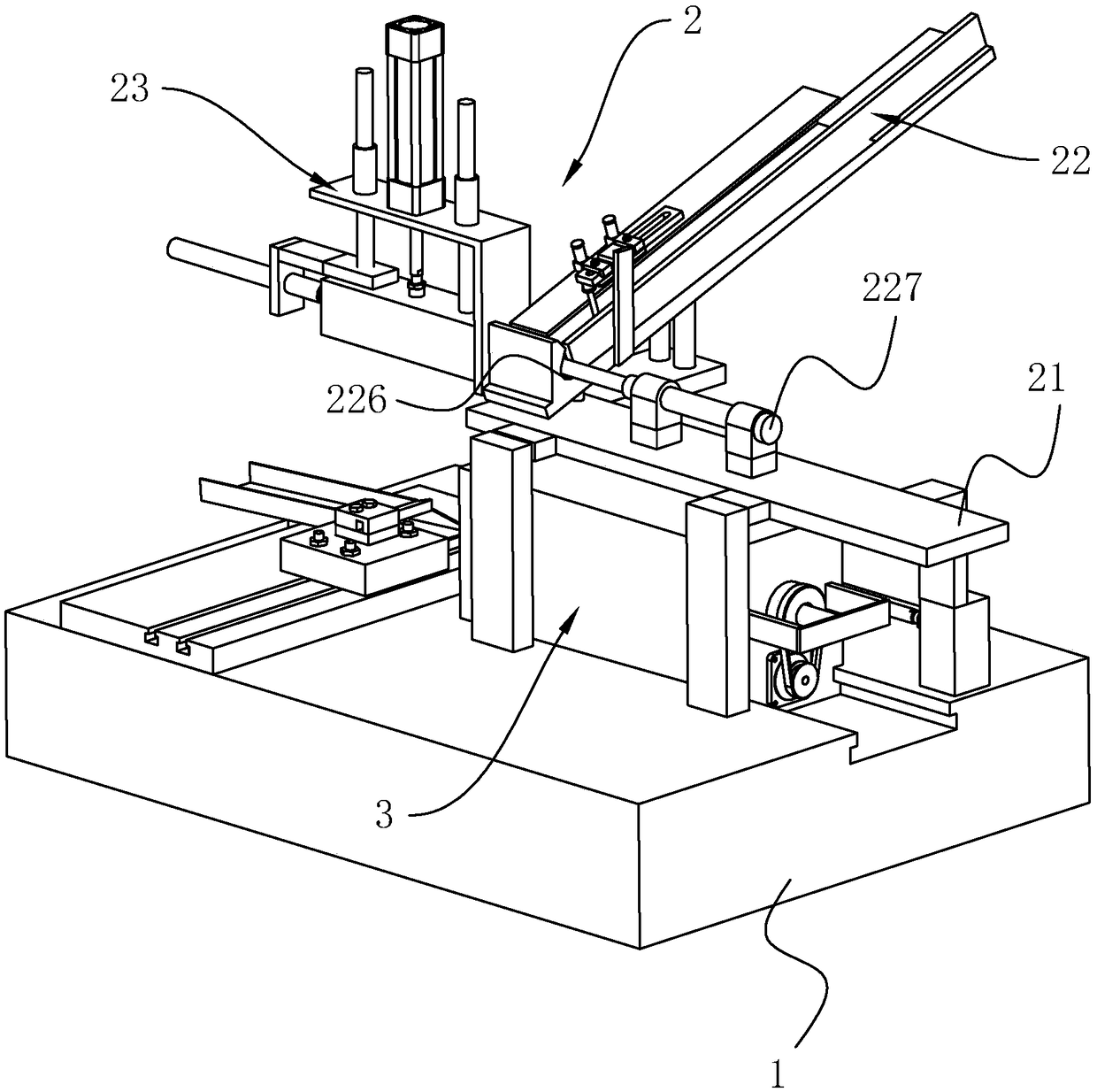
[0038] A pipe fitting processing lathe with automatic feeding, see figure 1 , including a base 1 , a feeding device 2 and a clamping and cutting device 3 . The clamping and cutting device 3 is located on the top surface of the base 1 , and the feeding device 2 is located above the clamping and cutting device 3 .

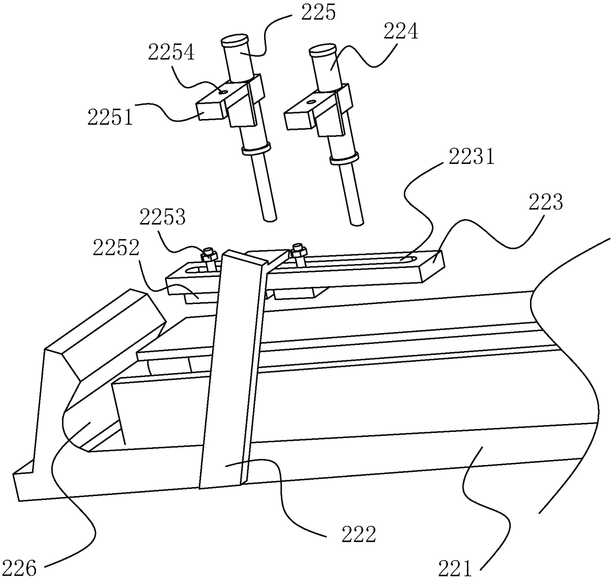
[0039] see figure 1 The feeding device 2 includes a bracket 21 fixed on the top of the base 1 , a feeding mechanism 22 fixed on the bracket 21 , and a fe...


PUM


Abstract

The invention discloses a pipe machining lathe with an automatic feeding function, and belongs to the field of pipe machining. According to the technical scheme, the pipe machining lathe with the automatic feeding function comprises a base, a clamping and cutting device and a feeding device, wherein the clamping and cutting device is arranged on the top of the base; the feeding device is positioned above the clamping and cutting device and comprises a support, a feeding mechanism and a conveying mechanism; the support is fixedly arranged on the upper surface of the base; the feeding mechanismis arranged on the support; the conveying mechanism is connected to one side of the feeding mechanism; the feeding mechanism comprises a feeding groove, a feeding cylinder and a separating cylinder; the feeding groove is obliquely formed in the top surface of the support; the feeding cylinder is detachably and fixedly connected to the side, which is close to the support, of the feeding groove; a groove is formed in the side, which is close to the support, of the feeding groove; and a first pushing cylinder is arranged on one side of the groove. The problem of manual feeding is solved, the effect of improving efficiency is achieved, and the pipe machining lathe with the automatic feeding function is mainly used for pipe machining equipment.

Description

technical field [0001] The pipe fitting processing equipment of the present invention particularly relates to a pipe fitting processing lathe with automatic feeding. Background technique [0002] A lathe is a machine tool that mainly uses a turning tool to turn a rotating workpiece. Drills, reamers, reamers, taps, dies and knurling tools can also be used for corresponding processing on the lathe. [0003] In the field of mechanical processing, for the processing of pipe parts, the pipe parts are generally set on a clamping fixture. The diameter of the rear part of the clamping fixture is the same as the inner diameter of the tube of the part to be processed. The cutter head on the pipe can be turned for pipe fittings. [0004] The existing Chinese patent whose authorized announcement number is CN202621925U can be referred to, which discloses a vertical lathe for processing pipe fittings, a vertical lathe for processing pipe fittings suitable for processing rotary iron cast...

Claims


Application Information

Patent Timeline
Patent Type & Authority Applications(China)
IPC IPC(8): B23B13/12B23B29/12
CPCB23B13/121B23B13/123B23B29/12
Inventor 李玉程张海卫
Owner 青岛铭和锐金属有限公司
Why Eureka
Try Eureka