Grinding method for kidney-shaped punch

A waist-shaped and punch technology is applied to the waist-shaped punch profiling grinder and its grinding field, which can solve the problems of difficult grinding, low efficiency, poor quality, etc. Accuracy and wear resistance, the effect of less surface grinding

Inactive Publication Date: 2018-09-04
ANHUI JACO NC MACHINE MFG
View PDF2 Cites 0 Cited by
  • Summary
  • Abstract
  • Description
  • Claims
  • Application Information

AI Technical Summary

Problems solved by technology

[0009] Aiming at the problems of high difficulty, low efficiency and poor quality in the grinding process of the existing waist-shaped punches, the invention provides a waist-shaped punch profiling grinder and its grinding method. The shape of the designed master makes the position of the contact point between the waist-shaped punch and the grinding wheel unchanged during the grinding process, and realizes the uniform grinding of the outer surface of the waist-shaped punch; the device clamps the waist-shaped punch once, One-time grinding process greatly improves the grinding quality and efficiency; the grinding method using the waist-shaped punch profiling grinder has small grinding and high precision, and the surface finish of the waist-shaped punch is high after grinding

Method used


Image

  • Grinding method for kidney-shaped punch
  • Grinding method for kidney-shaped punch
  • Grinding method for kidney-shaped punch

Examples


Embodiment 1

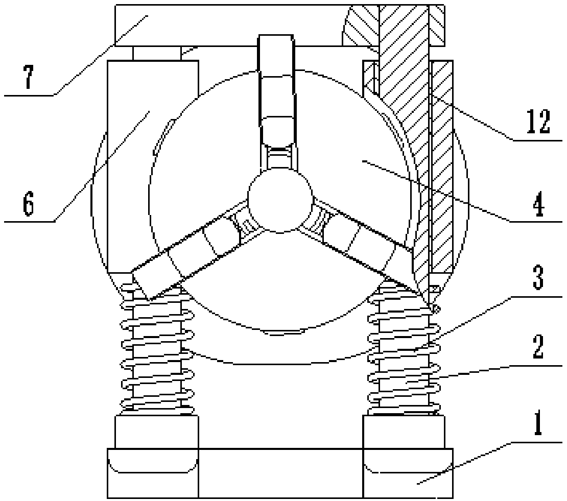
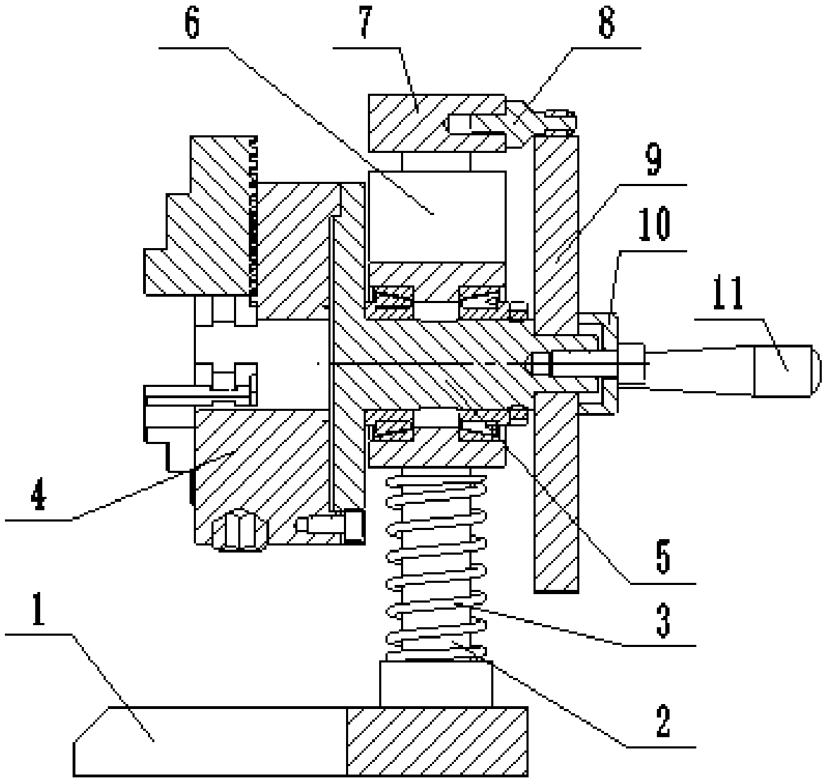
[0048] Such as figure 2 , image 3 and Figure 4 As shown, a waist-shaped punch profiling grinder of this embodiment includes a bottom plate 1, a spring 3, a chuck 4 and a main shaft 5; wherein, the bottom plate 1 is a "U"-shaped plate structure, and the While reducing the weight of the whole device, the support stability is ensured. Two vertical guide rods 2 are arranged in parallel and spaced apart on the bottom plate 1, and a sliding block 6 is sleeved on the two guide rods 2 . combine Figure 6 Specifically, in this embodiment, the sliding block 6 is provided with two guide holes 603 respectively matched with the two guide rods 2, and the two guide rods 2 respectively pass through the two guide holes 603, and each guide hole 603 Two guide sleeves 12 are arranged inside, and the guide sleeve 12 adopts a wear-resistant copper sleeve, which reduces the frictional resistance of the sliding block 6 moving on the guide rod 2, and improves the grinding quality of the waist-sh...

Embodiment 2

[0061] A waist-shaped punch profiling grinder of this embodiment has the same structure as that of Embodiment 1.

[0062] The waist-shaped punch is ground by the above-mentioned waist-shaped punch profiling grinder, and the steps are:

[0063] 1) Before installing the master form 9, use the chuck 4 to clamp the waist-shaped punch, turn the chuck 4, and measure the radial runout of the waist-shaped punch with a dial gauge to ensure that the radial circular runout of the waist-shaped punch is Proceed to the next step after not greater than 0.05mm;

[0064] 2) Install the former 9 on the main shaft 5, so that the upper side of the former 9 is in close contact with the guide wheel 802 of the guide wheel mechanism 8;

[0065] 3) Adjust the position of the limit plate 7 on the guide rod 2, so that the sliding block 6 compresses the spring 3, and the precompression of the spring 3 is ξ, ξ=βF / k; where β is 1-1.2, and F is 60 -100N, k is the elastic coefficient of spring; In the pres...

Embodiment 3

[0071] A waist-shaped punch profiling grinder of this embodiment has the same structure as that of Embodiment 1.

[0072] The waist-shaped punch is ground by the above-mentioned waist-shaped punch profiling grinder, and the steps are:

[0073] 1) Before installing the master form 9, use the chuck 4 to clamp the waist-shaped punch, turn the chuck 4, and measure the radial runout of the waist-shaped punch with a dial gauge to ensure that the radial circular runout of the waist-shaped punch is Proceed to the next step after not greater than 0.05mm;

[0074] 2) Install the former 9 on the main shaft 5, so that the upper side of the former 9 is in close contact with the guide wheel 802 of the guide wheel mechanism 8;

[0075] 3) Adjust the position of the limit plate 7 on the guide rod 2, so that the sliding block 6 compresses the spring 3, and the precompression of the spring 3 is ξ, ξ=βF / k; where β is 1-1.2, and F is 60 -100N, k is the elastic coefficient of spring; In the pres...


PUM


Abstract

The invention discloses a grinding method for a kidney-shaped punch, and belongs to the field of special-shaped punch machining. The method comprises the steps that firstly, the kidney-shaped punch isclamped with a chuck, the chuck is rotated, and radial jumping of the kidney-shaped punch is measured with a dial indicator and adjusted; secondly, a copy die is installed on a main shaft, and the upper side face of the copy die closely makes contact with a guide wheel of a guide wheel mechanism; thirdly, the position of a limiting plate on a guide rod is adjusted to enable sliding blocks to press springs; fourthly, a grinding wheel grinding tool is close to the kidney-shaped punch, the lower side face of a grinding wheel makes contact with the outer side face of the kidney-shaped punch, andthe grinding wheel is started; fifthly, the copy die is rotated to conduct grinding machining on the kidney-shaped punch; and lastly, after grinding is completed, the grinding wheel is moved away, thechuck is loosened, the kidney-shaped punch is taken down, burrs and flanges of the kidney-shaped punch are removed, and kidney-shaped punch machining is completed. According to the grinding method for the kidney-shaped punch, clamping and grinding machining can be conducted on the kidney-shaped punch at a time, the efficiency is high, the grinding amount is small, the precision is high, and the surface smoothness of the ground kidney-shaped punch is high.

Description

[0001] This application is a divisional application of an invention patent application titled: A waist-shaped punch profiling grinder and its grinding method, the application number is: 201510897519.9, and the application date is: December 4, 2015. technical field [0002] The invention belongs to the field of processing special-shaped punches, and more specifically relates to a profiling grinder for waist-shaped punches and a grinding method thereof. Background technique [0003] The punch is a metal part installed on the stamping die, which performs continuous punching and punching operations to separate or plastically deform the processed material, thereby obtaining the required finished or semi-finished products. At present, the precision of punches produced by domestic professional manufacturers can reach ±0.002mm, and the shapes that can be processed are complex; the punches bear the expansion force of the blank during work, and have a great impact on the structural str...

Claims


Application Information

Patent Timeline
Patent Type & Authority Applications(China)
IPC IPC(8): B24B17/02
CPCB24B17/02
Inventor 费文彪
Owner ANHUI JACO NC MACHINE MFG
Why Eureka
Try Eureka