Gas distributor and gasification furnace

A gas distributor and conical distribution technology, which is used in the manufacture of combustible gas, feeding tools for gasification devices, and granular/powder fuel gasification, etc., can solve the problems of difficult maintenance, wear of jet tubes, and high manufacturing costs.

Active Publication Date: 2018-09-04
ENN SCI & TECH DEV
View PDF5 Cites 0 Cited by
  • Summary
  • Abstract
  • Description
  • Claims
  • Application Information

AI Technical Summary

Problems solved by technology

However, when the direction of the opening is horizontal, the gasification agent is injected into the center of the gasifier through the horizontal opening, which will cause the bubbles in the center to gather and easily form large bubbles; while the distribution of the flow field in the area outside the center flow field is weak In this way, on the one hand, the high-concentration oxygen injected by the central jet tube is easily entrained into the large bubbles, resulting in uneven oxygen dispersion.
And under high temperature conditions, the center jet tube is severely impacted and worn by the large bubbles in the center, resulting in short service life of the center jet tube, high manufacturing cost, and difficult maintenance; at the same time, due to the excessive momentum of the center flow field, it is easy to discharge slag in the center Large air bubbles are formed at the mouth of the gasifier, causing the material to fail to fall normally and affecting the slag discharge, which cannot guarantee the normal operation of the gasifier; The distribution plate surface of the gasifier and the angle between the distribution plate and the gasifier wall form a flow dead zone

Method used


Image

  • Gas distributor and gasification furnace
  • Gas distributor and gasification furnace
  • Gas distributor and gasification furnace

Examples


Embodiment 1

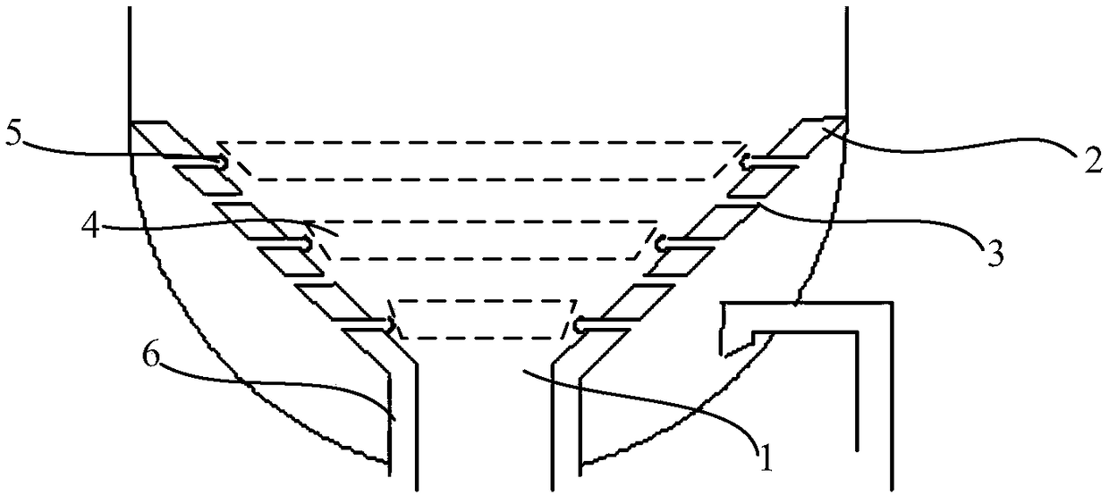
[0052] The high-temperature gasification process uses long-flame coal as the gasification raw material. The design of the gasifier adopts a centerless jet structure. During the gasification process, the coal particle size distribution is uniform (basically stable within the particle size range of 1mm-2mm), and the gas Distributors are used as figure 1 The structure shown, that is, the horizontal opening 3 on the conical distribution plate 2 adopts the horizontal opening 3 not connected to the air distribution structure 5 and the horizontal opening 3 connected to the air distribution structure 5 along the axial direction of the conical distribution plate 2. The holes 3 are arranged alternately. The air distribution structure 5 is an air distribution pipe 51 extending along the horizontal direction. Side connection, the second end is connected with a blocking member 53, the blocking member 53 includes a cylindrical connecting portion connected to the circumference of the second ...

Embodiment 2

[0054] The granular organic carbon material is used as the raw material for gasification. The design of the gasifier adopts a centerless jet structure, and the particle size distribution of the material is uniform during the gasification process (basically stable within the particle size range of 1mm-2mm). The gas distributor adopts Such as figure 1 The structure shown, that is, the horizontal opening 3 on the conical distribution plate 2 adopts the horizontal opening 3 not connected to the air distribution structure 5 along the axial direction of the conical distribution plate 2 and the horizontal opening 3 connected to the air distribution structure 5 3 alternately arranged, the air distribution structure 5 is an air distribution pipe 51 extending along the horizontal direction, the first end of the air distribution pipe 51 and the horizontal opening 3 are located on the inner ring surface side of the conical distribution plate 2 connection, the second end is connected with ...

Embodiment 3

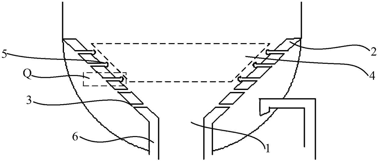
[0056] A kind of crushed garbage is used as the gasification raw material, and the design of the gasifier adopts a centerless jet structure. Since the particle size distribution of gasification raw materials is wide and there are more large particles, the gas distributor adopts image 3 The structure shown is similar to that of Embodiment 1. The air distribution structure 5 includes an air distribution pipe 51. The second end of the air distribution pipe 51 is closed by a blocking member 53. The outer surface of the recess on the blocking member 53 is Columnar structure, and the aperture of the horizontal opening 3 is 0.6 times the inner diameter of the cylindrical connection part on the blocking member 53, and the air distribution pipe 51 is provided with three air distribution holes 52 along the axial direction near the second end. The gas velocity of 52 is 0.9 times of the gas velocity of the horizontal opening 3. During the experimental operation, the slag discharge is sta...


PUM


Abstract

The invention relates to the technical field of chemical equipment, in particular to a gas distributor and a gasification furnace. The gas distributor can distribute part of airflow passing through horizontal openings along a vertical direction as required, so that the distribution of a flow field can be optimized, a flow dead zone caused by uneven distribution of the flow field can be avoided, smooth slag discharge can be realized, and the operation and maintenance cost of the gasification furnace can be reduced. The embodiment of the invention provides a gas distributor, which comprises a conical distribution plate with a slag discharge port at the bottom; the conical distribution plate is provided with a plurality of horizontal openings penetrating through inner and outer annular surfaces; the horizontal openings of the conical distribution plate corresponding to a first fluidization area are positioned on the inner side of the conical distribution plate and are connected with a gasdistribution structure respectively; and the gas distribution structure is used for re-distributing the air flow introduced into the horizontal openings of the conical distribution plate corresponding to the first fluidization area, so that the air flow passing through the horizontal openings of the conical distribution plate corresponding to the first fluidization area is uniformly dispersed ina vertical direction. The gas distributor provided by the embodiment of the invention is used for distributing gas in the gasification furnace.

Description

technical field [0001] The invention relates to the technical field of chemical equipment, in particular to a gas distributor and a gasifier. Background technique [0002] Fluidized bed coal gasification technology is one of the earliest industrialized gasification processes. The process is that the raw coal maintains continuous boiling and suspension state movement under the action of bottom-up gasification agent, and rapidly mixes and exchanges heat. gasification technology. As the main component of the fluidized bed equipment, the gasification agent distribution device (generally called "distribution plate" or "distributor") plays an important role in evenly distributing gas and supporting solid particles, and its shape and structure greatly affect the equipment. Production operation performance such as heat transfer and mass transfer. Specifically, the fluidized bed gas distributor is mainly used to evenly distribute the gasification agent, so that the gasification age...

Claims


Application Information

Patent Timeline
Patent Type & Authority Applications(China)
IPC IPC(8): C10J3/56C10J3/72
CPCC10J3/56C10J3/72C10J2200/15
Inventor 祖静茹刘雷李克忠怀俊天刘元杰
Owner ENN SCI & TECH DEV
Why Eureka
Try Eureka