Downlink high-temperature gasified product chilling device

A technology of chilling and product, applied in the field of descending high-temperature gasification product chilling device, can solve problems such as volume ratio difference, and achieve the effects of increasing volume concentration, increasing radiative heat transfer coefficient, and reducing the design of heating surface

Active Publication Date: 2016-05-25
SHANGHAI BOILER WORKS
View PDF2 Cites 1 Cited by
  • Summary
  • Abstract
  • Description
  • Claims
  • Application Information

AI Technical Summary

Problems solved by technology

Since gasification technology is the core shared technology of coal chemical technology, the produced CO and H 2 As raw material gas for downstream chemical production, H 2 The ratio requirement is higher, usually requires H 2 The /CO volume ratio reaches more than 2. Therefore, compared with the c

Method used


Image

  • Downlink high-temperature gasified product chilling device
  • Downlink high-temperature gasified product chilling device
  • Downlink high-temperature gasified product chilling device

Examples


Embodiment 1

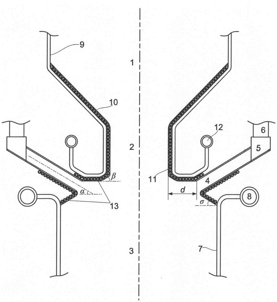
[0042] figure 1 Schematic diagram of the structure of the downward-type high-temperature gasification product quenching device provided for this embodiment. The downward-type high-temperature gasification product quenching device includes three main components, namely the gasification section, the quenching section, and the cooler section. .

[0043] The gasifier adopts the design of gas slag flowing downward, the gasifier adopts the water wall design, the tapered slag mouth at the bottom and the straight section of the slag mouth adopt coil type water cooling wall, and there is a ring-shaped chilling channel under the straight section of the slag mouth, and the chilling The front section of the channel is connected by a coil-type water-cooled wall, and the chilled gas header is used to distribute the synthesis gas, and the chilled gas is connected through the chilled gas inlet pipe. A syngas cooler is provided below the chilling channel. The body of the gasifier, the quench...

Embodiment 2

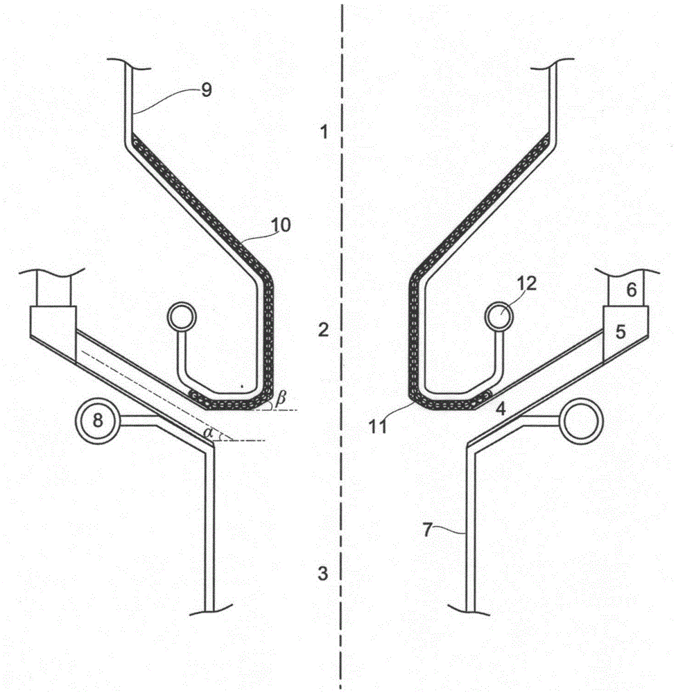
[0078] figure 2 The structure schematic diagram of the down-type high-temperature gasification product quenching device provided for this embodiment, the down-type high-temperature gasification product quenching device is basically the same as that of Example 1, the main difference is: the cylinder of the syngas cooler 3 The upper part of the water wall 7 is directly connected to the chilling channel 4, so the front section of the chilling channel 4 is directly connected to the cylinder water wall 7 of the syngas cooler 3, without the need for a coiled water wall 13; however, the chilling channel 4. The water-cooled wall coil 11 on the inner wall of the lower slag port 2 in the front section and the straight section is still connected by a coil-type water-cooled wall 13.


PUM


Abstract

The invention provides a downlink high-temperature gasified product chilling device which comprises a gasifying section, a chilling section and a cooler section. The gasifying section is used for generating a gasified product. The chilling section is used for chilling the gasified product generated by the gasifying section to enable the gasified product to be cured fast and lose cohesiveness. The cooler section is used for further cooling the product chilled by the chilling section and recovering waste heat. High-temperature synthesis gas with molten ash is chilled by low-temperature chilling gas nearby an outlet of a gasifying furnace, the temperature falls abruptly below an ash fusion point, the surface of slag is cured instantly, the slag is gathered to a center area to descend under carrying of chilling gas flow, the ash is prevented from falling into a synthesis gas cooler in a slag form to the maximum, and the situation that ash particles make contact with the water cooling wall face of the synthesis gas cooler and cause contamination is effectively prevented. Water vapor is adopted as the chilling gas, the shift reaction can be promoted, the volume fraction of H2 in the synthesis gas is greatly increased, and loads and shift cost of a follow-up shift system are greatly reduced. The system is easy to operate and has a large-scale application and popularization prospect.

Description

technical field [0001] The invention relates to a descending high-temperature gasification product quenching device, which belongs to the technical field of energy clean utilization. Background technique [0002] The product of the high-temperature and high-pressure entrained-bed gasification process has a large amount of high-level sensible heat for recycling, which can increase the system efficiency by 4-5 percentage points. However, under high-temperature gasification conditions, the ash particles are in a molten liquid state, which will cause contamination and slagging on the heating surface of the heat exchange system, and even cause slag blockage after the heat transfer deteriorates. Especially for the down-flow entrained gasifier, the syngas entrains a large amount of molten ash and flows downward. If the flow temperature is not controlled and directly enters the heat exchanger, it will cause a huge risk to the heating surface of the heat exchanger. [0003] The exis...

Claims


Application Information

Patent Timeline
IPC IPC(8): C10J3/72
CPCC10J3/72Y02P20/10Y02P20/129
Inventor 倪建军池国镇李平童川马伦
Owner SHANGHAI BOILER WORKS
Why Eureka
Try Eureka