
Novel workpiece rotating stand device applied to magnetron sputtering

A magnetron sputtering and working technology, applied in the field of magnetron sputtering, can solve the problems of inability to ensure the uniformity and consistency of the coating on the surface of the workpiece, reduce the coating effect, limit the development of the magnetron sputtering process, etc. Service life, enhance coating effect, solve the effect of uneven coating

Pending Publication Date: 2018-09-04
UNIV OF SCI & TECH LIAONING
View PDF10 Cites 1 Cited by
  • Summary
  • Abstract
  • Description
  • Claims
  • Application Information

AI Technical Summary

Problems solved by technology

With the wide application of magnetron sputtering, the singleness of the rotation mode of the workpiece turret inside the traditional magnetron sputtering chamber limits the further development of the magnetron sputtering process
Due to the limitation of the rotation mode, the uniformity and consistency of the coating on the surface of the workpiece cannot be guaranteed during the coating preparation process, which reduces the coating effect

Method used


Image

  • Novel workpiece rotating stand device applied to magnetron sputtering
  • Novel workpiece rotating stand device applied to magnetron sputtering
  • Novel workpiece rotating stand device applied to magnetron sputtering

Examples


Embodiment Construction

[0023] The present invention will be further described below in conjunction with accompanying drawing.

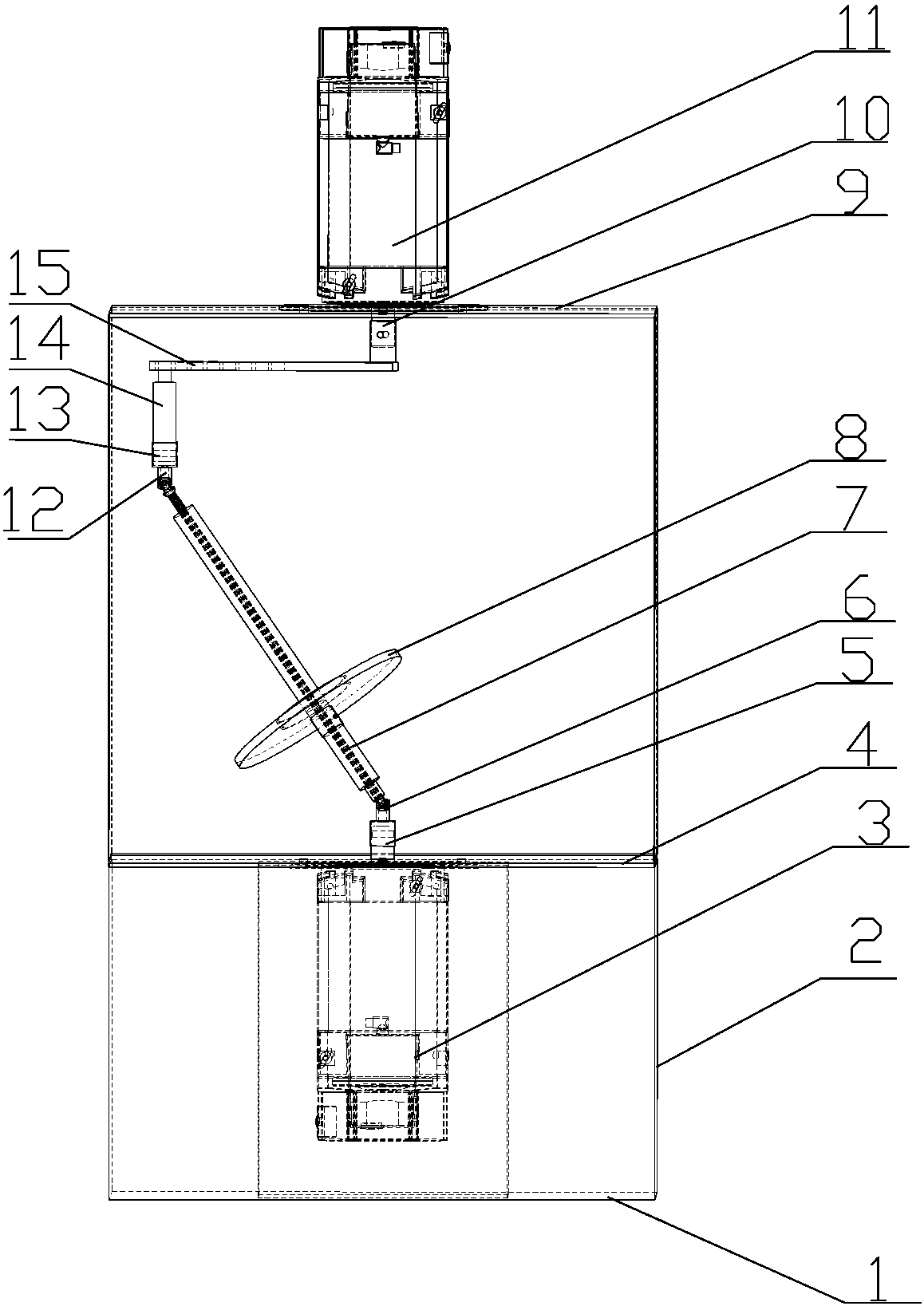
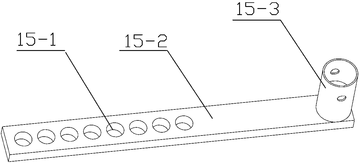
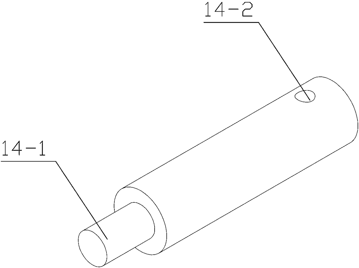
[0024] like Figure 1-5 As shown, a turret device for magnetron sputtering of the present invention includes a reaction chamber composed of a side wall 2, a top plate 9 and a bottom plate 1, a working tray 8, a spindle 7 and a working The tray movement mechanism is characterized in that a base 4 is provided in the reaction chamber, and the base 4 divides the reaction chamber into an upper chamber and a lower chamber, and the working tray 8 is arranged on the main shaft 7, so that Described workpiece tray 8 is that the upper end has the ring-shaped boss 8-1 that is used to fix the cylindrical workpiece, and the lower end has the disc of connecting sleeve 8-2, and its ring-shaped boss 8-1 is connected with the cylindrical workpiece. The inner diameter is an interference fit, and there is a pre-tightening screw hole 8-3 on the connecting sleeve 8-2. In this way, the workpiece...


PUM


Abstract

The invention relates to a rotating stand device applied to magnetron sputtering. The rotating stand device comprises a reaction cavity, a working tray, a spindle and a working tray moving mechanism,wherein the reaction cavity is composed of side walls, a top plate and a bottom plate, and the working tray, the spindle and the working tray moving mechanism are arranged in the reaction cavity. Therotating stand device is characterized in that a base station is arranged in the reaction cavity and divides the reaction cavity into an upper cavity body and a lower cavity body, and the working trayis arranged on the spindle; and the working tray moving mechanism comprises a rotation mechanism and a revolution mechanism. The rotating stand device has the beneficial effects that the disadvantagethat a traditional workpiece rotating stand is simplex in rotating mode is overcome, the degree of freedom of workpiece movement is increased, thus all faces of a workpiece can be evenly covered withparticles sputtered by target materials, the problem that coatings of seamed edges of the workpiece are uneven is effectively solved, and the effect of the coatings is enhanced.

Description

technical field [0001] The invention belongs to the field of magnetron sputtering, in particular to a novel workpiece turret device used in magnetron sputtering. Background technique [0002] With the development of science and technology, the surface modification of workpieces is used in more and more industrial fields. This method of surface modification greatly reduces the cost of frequent replacement due to the low life of parts, and also improves production efficiency. . [0003] Magnetron sputtering plays an important role as an important component in the surface modification of workpieces. With the wide application of magnetron sputtering, the singleness of the rotation mode of the workpiece turret inside the traditional magnetron sputtering chamber limits the further development of the magnetron sputtering process. Due to the limitation of the rotation mode, the uniformity and consistency of the coating on the surface of the workpiece cannot be guaranteed during ...

Claims


Application Information

Patent Timeline
Patent Type & Authority Applications(China)
IPC IPC(8): C23C14/50C23C14/35
CPCC23C14/35C23C14/505
Inventor 周艳文佟欣儒赵卓武俊生陈雪娇赵志伟张鑫方方张豫坤
Owner UNIV OF SCI & TECH LIAONING
Learn More