Modular steel frame

A steel frame and modular technology, applied in the direction of truss structure, joists, girders, etc., can solve the problems that it is difficult to give full play to the combination effect of double columns and double beams, increase the workload of on-site welding, and it is difficult to ensure the quality of welding, etc. Achieve the effects of reduced deformation, high assembly efficiency, and easy replacement and disassembly

Pending Publication Date: 2018-09-04
QINGDAO TECHNOLOGICAL UNIVERSITY
View PDF7 Cites 6 Cited by
  • Summary
  • Abstract
  • Description
  • Claims
  • Application Information

AI Technical Summary

Problems solved by technology

In the connection plate joint of the inner sleeve, the frame column of the upper and lower module units is welded vertically through the inner sleeve, and the inner sleeve is welded and connected through the connecting plate in the horizontal direction. The welding connection ensures the connection strength and stiffness of the node, but The workload of on-site welding is increased, the on-site welding construction is more difficult, and it is difficult to guarantee the quality of welding
In a word, the existing modular steel frame connected by the above-mentioned existing joint forms, due to the lack of effective connection between columns and beams or between beams and beams, will cause very large gaps between columns and beams in the joint form. With large gaps, the columns and beams of adjacent modular units cannot be effectively connected to form composite columns and composite beams. It is difficult to give full play to the composite effect of the double-column and double-beam modular steel frame structure, and the structure is prone to premature failure due to joints Or the frame beam-column section of a single module unit yields prematurely, resulting in the overall failure of the structure

Method used


Image

  • Modular steel frame
  • Modular steel frame
  • Modular steel frame

Examples


Embodiment Construction

[0035]In the following, the present invention will be specifically described through exemplary embodiments. It should be understood, however, that elements, structures and characteristics of one embodiment may be beneficially incorporated in other embodiments without further recitation.

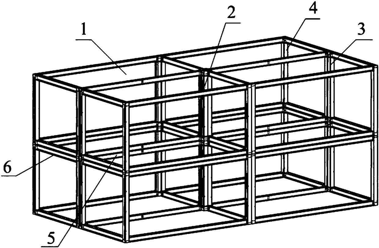
[0036] In the description of the present invention, it should be noted that the orientations or positional relationships indicated by the terms "inner", "outer", "upper" and "lower" are based on the attached figure 1 The positional relationship shown is only for the convenience of describing the present invention and simplifying the description, but does not indicate or imply that the referred device or element must have a specific orientation, be constructed and operated in a specific orientation, and therefore cannot be construed as limiting the present invention . In addition, the terms "first" and "second" are used for descriptive purposes only, and should not be understood as indicating...


PUM


Abstract

The invention provides a modular steel frame and belongs to the technical field of structural engineering. According to the modular steel frame, the double-column and double-beam combined effect can be brought into full play. The modular steel frame comprises a plurality of same modular unit layers. Each modular unit layer comprises a plurality of modular units, and each modular unit is a box-typeframe formed by a frame column and a frame beam which are connected. The modular steel frame further comprises a connecting assembly which comprises inner sleeves, column connecting bolts and beam connecting bolts. In the same modular unit layer, the four frame columns in the middle are connected into a combined middle column through the corresponding column connecting bolts, the two frame columns on the outer side face are connected into a combined side column through the corresponding column connecting bolts, and the frame columns at the corners are corner columns. In every two adjacent modular unit layers, the vertically-adjacent two combined middle columns, two combined side columns and two corner columns are connected through the inner sleeves correspondingly. In every two adjacent modular unit layers, the four frame beams in the middle are connected into a combined middle beam through the corresponding beam connecting bolts, and the two frame beams on the outer side faces are connected into a combined edge beam through the corresponding beam connecting bolts.

Description

technical field [0001] The invention belongs to the technical field of structural engineering, in particular to a modular steel frame. Background technique [0002] The modular steel frame structure has the characteristics of high bearing capacity and flexible size selection, and has broad development prospects. Different from ordinary steel frame structures, modular steel frames are usually composed of multiple modular units connected, and each modular unit is a box frame formed by connecting frame columns and frame beams; in modular steel frames, multiple The modular units are arranged in multiple rows, columns and multi-layers, wherein the opposite side surfaces of every two adjacent modular units are attached to each other. After connection, the position of the central column of the modular steel frame is the four adjacent frame columns on the upper floor and the four adjacent frame columns on the lower floor, a total of eight frame columns; the position of the side col...

Claims


Application Information

Patent Timeline
Patent Type & Authority Applications(China)
IPC IPC(8): E04B1/19E04B1/58E04C3/06E04C3/32
CPCE04B1/1903E04C3/06E04C3/32
Inventor 王燕郏书朔安琦杨怡亭
Owner QINGDAO TECHNOLOGICAL UNIVERSITY
Why Eureka
Try Eureka