CFST thin wall box-type section component

A cross-section and thin-walled technology, which is applied in the direction of load-bearing elongated structural components, building components, arched beams, etc., can solve the problems of welding residual stress and poor stability of steel thin-walled box-shaped components, and achieve construction speed Reusable, fast construction, good seismic performance

Inactive Publication Date: 2017-07-21
NANJING INST OF TECH
View PDF5 Cites 0 Cited by
  • Summary
  • Abstract
  • Description
  • Claims
  • Application Information

AI Technical Summary

Problems solved by technology

[0003] The purpose of the present invention is to provide a thin-walled box-section member of concrete filled stee...

Method used


Image

  • CFST thin wall box-type section component
  • CFST thin wall box-type section component
  • CFST thin wall box-type section component

Examples


Embodiment 1

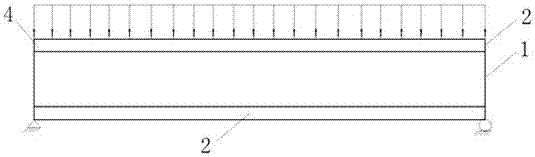
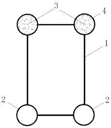
[0035] combine figure 1 , figure 2 As shown, the CFST member of this embodiment is a closed box section, the steel pipe is located at the corner of the section, and the steel pipe 2 is welded to the thin-walled steel plate 1 . The steel pipe 2 located on the compression side of the entire section and the axis is filled with concrete 3 to form a steel pipe concrete 4 to bear the compressive stress caused by the bending moment, which can effectively improve the bending bearing capacity of the entire member, and the section located at the center and axis is subjected to tension and compression The steel pipe 2 on one side is not filled with concrete 3, which can effectively reduce the dead weight and cost of the whole component. The cross-section of the components in this embodiment is rectangular as a whole, and can also be designed as other polygonal cross-sections such as squares, triangles, and trapezoids. The components can be disassembled into several parts for factory pr...

Embodiment 2

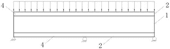
[0039] combine image 3 , Figure 4 , The difference between the structure of this embodiment and Example 1 is that all steel pipes 2 are filled with concrete 3 to form steel pipe concrete 4 . The figure is a box-shaped cross-section member, and it can also be designed as a cross-sectional form of square, triangle, trapezoid and other polygonal shapes. Components can be split into several parts for factory prefabrication and on-site welding and assembly. Other components are the same as in Embodiment 1.

Embodiment 3

[0041] combine Figure 5 , Figure 6 As shown, this implementation part is a CFST thin-walled box-shaped member bearing axial pressure, steel pipe 2 and concrete 3 filled in the box-shaped section to form steel pipe concrete 4 . The figure is a box-shaped cross-section member, and it can also be designed as a cross-sectional form of other polygonal shapes such as a square, a triangle, and a trapezoid. Components can be split into several parts for factory prefabrication and on-site welding and assembly. Other components are the same as in Embodiment 1.


PUM

PropertyMeasurementUnit
Thicknessaaaaaaaaaa
Thicknessaaaaaaaaaa

Abstract

The invention relates to a CFST thin wall box-type section component and belongs to novel steel tube concrete components. The CFST thin wall box-type section component comprises a steel tube, a thin wall steel plate and concrete. The thin wall rectangular section is formed by the steel tube and the thin wall steel plate. The steel tube is located at the corner of the thin wall rectangular section. The interiors of closed spaces separated by the steel tube and the thin wall steel plate are filled with the concrete to form concrete-filled steel tubes. The steel tube and the thin wall steel plate are welded together. According to the component, the steel tube is arranged at the corner of the whole section, and the problem that serious residual stress exists in a traditional steel thin wall box-type component is effectively solved. Once the interiors of the steel tube and the thin wall rectangular section are filled with the concrete to form the concrete-filled steel tube components, the composite effect between the concrete and steel can be sufficiently exerted. The CFST thin wall box-type section component has the characteristics of being light, high in strength, good in stability and anti-seismic property, high in construction speed, capable of being reused and the like.

Description

technical field [0001] The invention relates to steel pipe concrete components, in particular to a CFST thin-walled box-shaped section component. Background technique [0002] At present, the concrete filled steel pipe members in the housing construction in our country mainly use the inner filling concrete of steel pipes or square steel pipes as structural load-bearing members. Concrete-filled steel tube members can be used not only as flexural members, axial compression members, but also as compression-bending (tension-bending) members and applied to various parts of the building structure. There are at least three problems in traditional steel thin-walled box members. One is that butt welds are used for welding the steel plates at the corners. For thick plates, the welding process is complicated, and it is easy to produce large welding residual stress and welding residual deformation; When the section height is high, the steel plate of the web is prone to local buckling, ...

Claims


Application Information

Patent Timeline
IPC IPC(8): E04C3/293E04C3/46
CPCE04C3/293E04C3/46
Inventor 过轶青张文福赵文艳耿方方臧华肖同亮
Owner NANJING INST OF TECH
Why Eureka
Try Eureka