
Overhanging part of non-removable formwork system

A technology that does not need to dismantle formwork and pick parts, which is applied to building components, building reinforcements, structural elements, etc., can solve the problems of storage, maintenance, transportation, hoisting, inconvenient installation, waste of resources, hidden dangers, etc., to facilitate later transportation. , The effect of reducing self-weight and effective connection

Pending Publication Date: 2018-09-04
李凤东
View PDF15 Cites 0 Cited by
  • Summary
  • Abstract
  • Description
  • Claims
  • Application Information

AI Technical Summary

Problems solved by technology

[0002] In traditional construction, steel bars are processed on the construction site, steel bars are bound, formwork is supported, and concrete is poured; workers cannot accurately control whether the verticality of the wall meets the specification requirements when supporting formwork. Waste of resources, environmental protection issues, potential safety hazards and frequent accidents, high labor intensity, low degree of construction mechanization, relatively low work efficiency
[0003] In the original prefabricated system, the concrete protective surface layer was poured in the factory in advance, which caused great inconvenience in the later storage, maintenance, transportation, hoisting, and installation, and the difficulty of repairing damage was relatively large.
[0004] In the existing prefabricated concrete sandwich insulation free formwork system, the reinforced mesh of the concrete protective surface layer is suspended by the connectors, and the protective layer is not effectively suspended from the main body; the hanging point needs to be installed separately, and the external support needs to be separately installed. Fix with pull bolts

Method used


Image

  • Overhanging part of non-removable formwork system

Examples


Embodiment Construction

[0016] Embodiments of the present application will be described in detail below with reference to the drawings and examples.

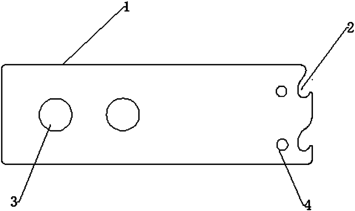
[0017] Such as figure 1 As shown, the present invention provides a pick-up part of the formwork system without dismantling, which is a plate-shaped body, and one end of the plate-shaped body is provided with a hook; the end of the plate-shaped body far away from the pick-up hook is provided with a hanging point hole The mechanism makes the structure simpler and reduces the weight of the component itself; a connection hole is provided near the pick hook, which can be more effectively connected with the internal support system.

[0018] Further, the end of the plate-shaped body is provided with an inwardly recessed hook groove to form the lifting hook. The pick hooks are connected to the external support points to effectively fix the reinforcement mesh of the protective surface layer and ensure the thickness of the concrete protective layer of the reinf...


PUM


Abstract

The invention provides an overhanging part of a non-removable formwork system. The overhanging part of the non-removable formwork system is a plate-shaped body. An overhanging hook is arranged at theone end portion of the plate-shaped body, and the overhanging hook is connected with an external supporting point and is used for fixing a protective surface layer reinforcing bar mesh. A hanging point hole is formed in the one end, away from the overhanging hook, of the plate-shaped body. A connecting hole is formed in the one end, near the overhanging hook, of the plate-shaped body. The overhanging part spans a whole element and an insulation layer, the overhanging hook is connected with the protective surface layer reinforcing bar mesh effectively, so that the element form a whole body, theself-weight of the element is reduced, and later transportation is facilitated. After pouring, the main part can effectively support the weight of an external surface layer, so that the overall performance of the true sandwich insulation and non-removable formwork system is achieved, problem of hanging point is solved, the main part is effectively connected with an internal supporting system, andthe problems of storage, maintenance, transportation, hanging, installation and the like of a concrete protective surface layer in the later period of pouring in a plant are solved.

Description

technical field [0001] The application relates to the technical field of building material components, in particular to a pick-up part of a formwork system without dismantling. Background technique [0002] In traditional construction, steel bars are processed on the construction site, steel bars are bound, formwork is supported, and concrete is poured; workers cannot accurately control whether the verticality of the wall meets the specification requirements when supporting formwork. Waste of resources, environmental protection issues, potential safety hazards and frequent accidents, high labor intensity, low degree of construction mechanization, and relatively low work efficiency. [0003] In the original prefabricated system, the concrete protective surface layer was poured in the factory in advance, which caused great inconvenience in the later storage, maintenance, transportation, hoisting, and installation, and the damage repair was relatively difficult. [0004] In th...

Claims


Application Information

Patent Timeline
Patent Type & Authority Applications(China)
IPC IPC(8): E04C5/16E04C5/18
CPCE04C5/16E04C5/18
Inventor 李凤东
Owner 李凤东
Learn More