Rotor structure and engine

A technology of rotor structure and rotating body, which is used in engine components, machines/engines, liquid fuel engines, etc., can solve the problems of difficult processing of rotating shafts, high processing costs, long processing time, etc., to reduce processing costs and prolong service life. Effect

Active Publication Date: 2018-09-04
SHENZHEN YIDONG AVIATION TECH CO LTD
View PDF6 Cites 2 Cited by
  • Summary
  • Abstract
  • Description
  • Claims
  • Application Information

AI Technical Summary

Problems solved by technology

The traditional rotor structure is to realize the smooth and high-speed rotation of the compressor impeller, shaft and turbine at more than 100,000 revolutions per minute. Therefore, it is necessary to maintain a high degree of verticality between the rigid connection between the compressor and the shaft and the rigid connection between the turbine and the shaft. The precision machining and assembly of the machine, the shaft and the turbine can make the rotor structure not get stuck or worn out with the bearing during high-speed rotation. Materials have higher requirements
Especially when the shaft is longer, the strength requirements for the shaft are higher, and the processing difficulty and cost of the shaft are greater

Method used


Image

  • Rotor structure and engine
  • Rotor structure and engine
  • Rotor structure and engine

Examples


Embodiment Construction

[0049] In order to make the technical problems solved by the present invention, the technical solutions adopted and the technical effects achieved clearer, the technical solutions of the present invention will be further described below in conjunction with the accompanying drawings and through specific implementation methods. It should be understood that the specific embodiments described here are only used to explain the present invention, but not to limit the present invention. In addition, it should be noted that, for the convenience of description, only the parts related to the present invention are shown in the drawings but not all of them.

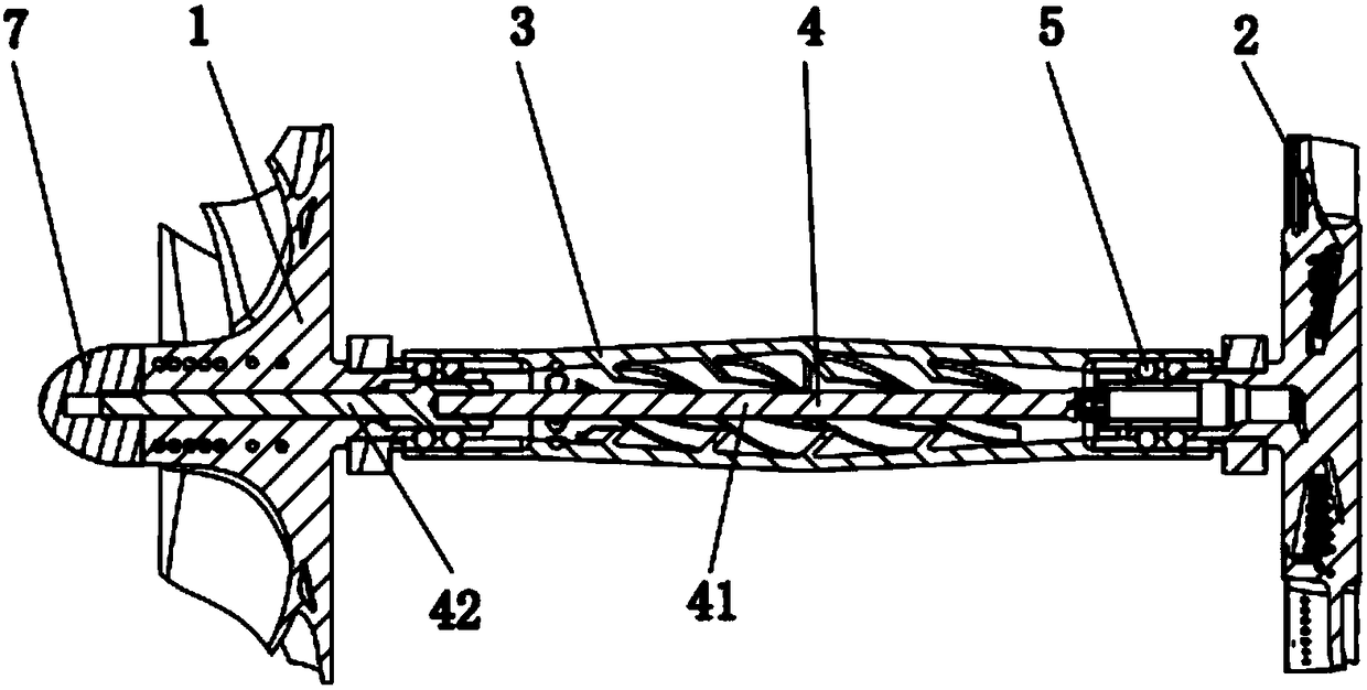
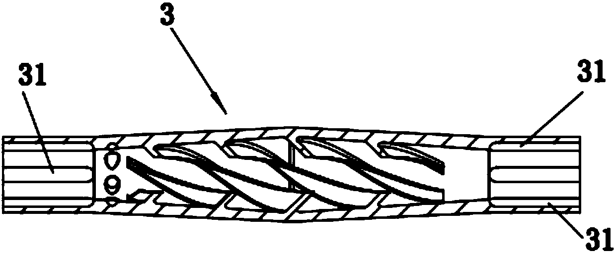
[0050] This embodiment discloses a rotor structure, such as figure 1shown. The rotor structure includes a compressor 1 , a turbine 2 , a torque transmission sleeve 3 and a locking tie rod 4 . Among them, one end of the torque transmission bushing 3 is connected to the compressor 1 through the first transmission connection part, and...


PUM


Abstract

The invention discloses a rotor structure and an engine, and belongs to the technical field of aero-engine equipment. The rotor structure comprises an air compressor, a turbine, a transmission torsionshaft sleeve and a locking pull rod. One end of the transmission torsion shaft sleeve is in transmission connection with the air compressor through a first transmission connection part, and the otherend of the transmission torsion shaft sleeve is in transmission connection with the turbine through a second transmission connection part. The locking pull rod penetrates through the transmission torsion shaft sleeve. The two ends of the locking pull rod are connected with the air compressor and the turbine separately. The first transmission connection part and/or the second transmission connection part are flexible transmission connection parts. According to the rod structure and the engine, under the combined effect of the transmission torsion shaft sleeve, the locking pull rod and the flexible transmission connection parts, flexible connection and transmission of the turbine and the air compressor are achieved; and automatic adjustment can be achieved to a certain extent in the high-speed rotating process of the engine so that the transmission torsion shaft sleeve, the locking pull rod and the flexible transmission connection parts can rotate separately around self axes, and accordingly, the requirements for the coaxiality, assembly precision and machining of all components of a rotor are lowered.

Description

technical field [0001] The invention relates to the technical field of aero-engine equipment, in particular to a rotor structure and an engine. Background technique [0002] Aeroengine is a highly complex and precise thermal machinery, which directly affects the performance, reliability and economy of aircraft, and is an important manifestation of a country's technological, industrial and national defense strength. The structural performance of the rotor of an aero-engine directly affects the performance of the engine. [0003] In the prior art, the rotor structure includes a cold-end centrifugal compressor impeller, a rotating shaft and a hot-end turbine. The two ends of the rotating shaft are respectively connected to the compressor and the turbine. Through the rigid connection between the rotating shaft and the compressor and the turbine, the simultaneous Rotation, that is, the rotating shaft not only needs to realize the connection with the compressor and the turbine du...

Claims


Application Information

Patent Timeline
Patent Type & Authority Applications(China)
IPC IPC(8): F02C3/08F01D5/02F04D29/28
CPCF01D5/021F02C3/08F04D29/284
Inventor 韩品连张坤张自印
Owner SHENZHEN YIDONG AVIATION TECH CO LTD
Why Eureka
Try Eureka